
Project hardware requirement
- One 89c52 or 89c51 microcontroller
- Bread board or PCB (Making Circuit)
- 16×2 lcd (Displaying Text)
- 4×4 keypad (Taking Input)
- Potentiometer (For setting lcd contrast)
- Crystal(11.0592 MHz)
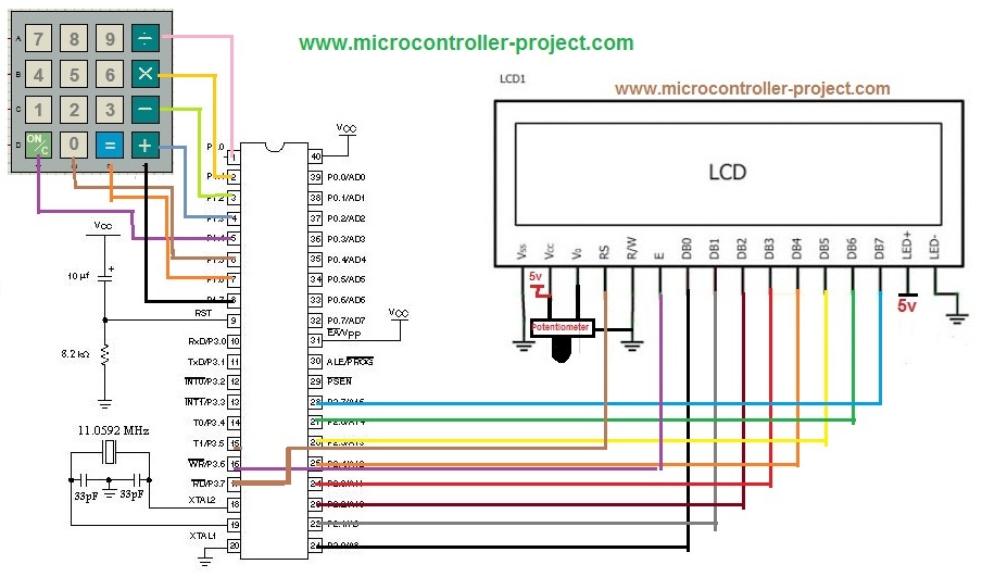
Calculator with 8051 microcontroller circuit diagram
8051 calculator project code
Starting from the beginning, the first line of the code. Don’t forget to include reg51.h header file to your every project that contains an 8051(89c51,89c52) microcontroller in it. This header file is very important. Keil compiler checks this header file in your code first. If it is present compiler compiles your code, absence of this header file will lead to an error. Next some functions declarations.
Functions in 8051 calculator code
- Sending COMMANDS to lcd. (If you dont know about commands just click the commands word)
void lcddata(unsigned char)
- Sending DATA to lcd. (If you dont know about Data just click the data word)
void MSDelay(unsigned int)
- Generating Delay.
void disp_num(float num)
- Displaying number on lcd after calculation.
int get_num(char ch)
- Turning Character to Number
void lcdinit()
- Initializing lcd chipset driver. (click the link to see what it means Initializing lcd)
char scan_key(void)
- Scanning a number from keypad.
8051 calculator main() function of code
Scan_key() is reading the key as character. To perform arithmetic operation on the key we have to convert it in number. get_num(key) is doing this work for us. Then lcddata() function is printing the character on lcd and lcdcmd (0x01) command clears all the contents of lcd.
Than the next string prints on lcd saying operator = . You have to enter the operator and all the previous steps are repeated. Than the next string appears saying Enter 2 no= Just enter the no. Now you see a switch statement it is making decision if the operator you entered is + it will go for disp_num(K1+k2) function by adding the two number you just entered. For – operator it will go for negation and for other operators it will for them. Sending commands and data to lcd is very import function its brief detail is available at Lcd data & Command function. Than delay function to put some delay in the process it is very important . One can understand it when running the embedded code in hardware equipment’s. scan_key() function is explained on the following link 4×4 keypad programming.
The disp_num() function is displaying our calculated number on 16×2 lcd.
sfr’s are direct memory locations to ports, registers and timers of 8051 microcontrollers. Sfr ldata=0xA0 is accessing Port-2 of microcontroller. 0xA0 is Sfr to Port-2. Now ldata is a variable that is pointing to Port-2 of microcontroller. Then some pins are declared. Lcd is Controlled by Port-3 pins# 5,6,7 . Lcd data pins are connected to Port-2 of Microcontroller. Port-1 is Scanning rows and coulombs of 4×4 keypad.
Now how it is working?
Character arrays and sfr’s used in calculator functions
Filed Under: 8051, Electronic Projects, Microcontroller Projects

Questions related to this article?
👉Ask and discuss on Electro-Tech-Online.com and EDAboard.com forums.
Tell Us What You Think!!
You must be logged in to post a comment.