Summary of the circuit-
Principle behind Circuit-
This circuit is quite pocket-friendly and at the same time, simple to build. Components like 555 timer, capacitor, transistors, inductor and few resistors are needed to construct the circuit.
When a new call comes, this circuit will provide you an optical effect by flashing an LED. It can be useful in situations where you can’t keep your phone on ringing mode like while working in the office or at home when somebody is sleeping or even when you don’t wish to hear the tone and need some silence. This circuit can also be used in places where there is a lot of noise due to which you are not able to hear the ringtone of your cell phone.
When someone calls you, the transmitter inside your cell phone is triggered and about 900MHz of frequency is transferred by it. Now the inductor L1 catches this frequency produced by the transmitter of mobile and passes it to transistor T1,that comes into active state. Now by the collector end of transistor, IC1 will receive the input through pin 2. As IC1 gets triggered, the LED which is coupled with pin 3 if IC1 will flash and you’ll get to know that you have a call.
Components required building the circuit-
IC
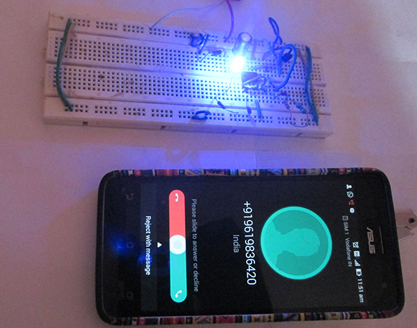
Fig. 1: Prototype of 555 IC based Mobile Call Indicator Circuit designed on a breadboard
Circuit Diagrams

Project Components
Project Video
Filed Under: Electronic Projects
Filed Under: Electronic Projects

Questions related to this article?
👉Ask and discuss on Electro-Tech-Online.com and EDAboard.com forums.
Tell Us What You Think!!
You must be logged in to post a comment.