Summary:
This Article is to explain some of the basics of CAN and show how choosing CAN for embedded systems networked applications beneficial.
In today’s world, every industry need is automation so the industries will need automation, protocol, this project focused on a system in which CAN protocol is used to monitor and control 4 different devices by single Arduino called as master and another Arduino called as a slave. Implementation of CAN protocol, which is a message based protocol, the single master will broadcast short messages which are to be received in the at multiple slave locations simultaneously.
Description:
Prerequisites & Equipment:
You are going to need the following:
-
Two Arduino Board or Arduino clone(Here is a guide if you need)
-
A 5v TTL -UART Bluetooth module.
-
LCD, Relays and its Driving circuits.
-
Arduino IDE for the programming.
-
Two CAN Tranciever
Controller Area Network (CAN) Protocol was initially created by German automotive system developer Robert Bosch in the mid of-1980s for automotive applications as a method for enabling robust serial communication. The aim was to make automobiles more reliable, robust and safe while decreasing wiry tension, weight and complexity. Since its acceptance, the CAN protocol has gained worldwide popularity in industrial automation and automotive/truck applications. For more details refer this article.
As our project is a single master message broadcast system that is suitable for systems where data contained in short messages are sent simultaneously to the other devices in other locations. As CAN protocol is not an address based messaging procedure, messages are not addressed to the exact slaves, but the sender’s identifier that is included in a message not only helps the receiver to know the data it contains but also tells the receiver to keep the data or ignore it if it is not intended to it.
Working Principle:
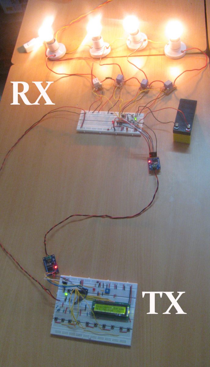
This Project includes two distinct parts, Display section and a Control section. Transmitter section consists of LCD to show the status of devices and the control switches. The receiver section consists of relay circuits with Optocoupler protection. The communication between both sections are carried out by the MCP2515 CAN transceiver.
For more details about CAN protocol interface with Arduino refer Getting Started with CAN interface with Arduino.
The DISPLAY Section:
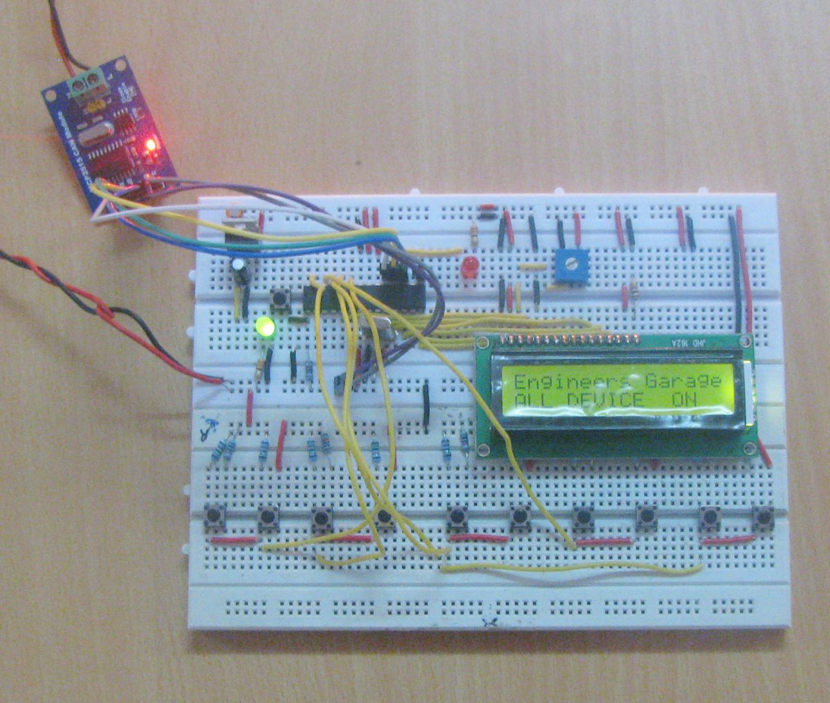
DISPLAY section consists of an Arduino with a MCP2515 CAN module and an TJA1040 transceiver chip. The Microcontroller is operated from a 16MHz crystal. And MCP2515 has an SPI interface which is used to connect using SPI pins in Arduino. The Pins CANH and CANL of the transceiver chip are connected to the CAN bus. LCD is connected to Arduino to display the status of the devices and Switches are connected to send control data to the Control Section.
The CONTROL Section:
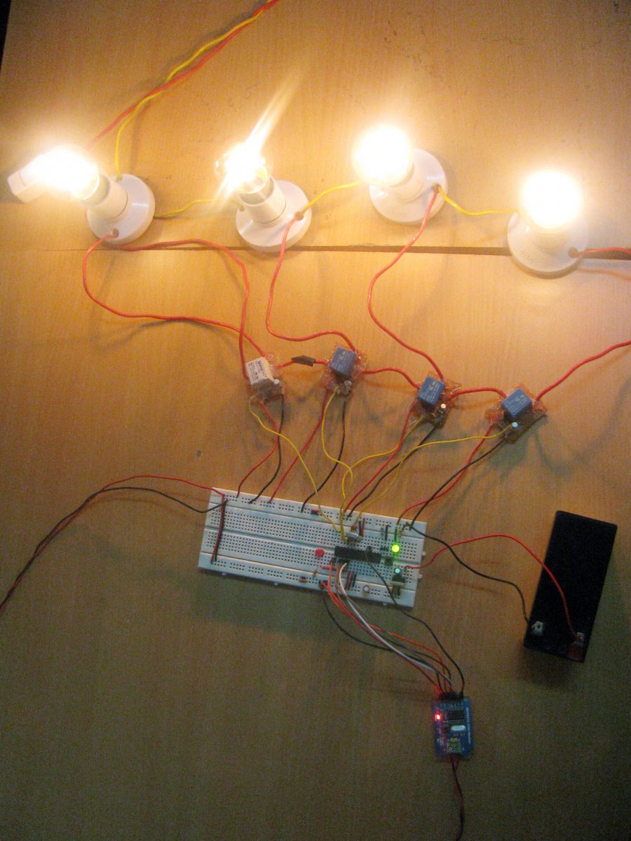
The COLLECTOR section consists of an Arduino with a MCP2515 CAN module and an TJA1040 transceiver chip. The Digital pins of Arduino are used to controlling the Relays, which in turn ON the Devices in the Industry. For Real Time Switching of the Devices Interrupt based message reception is used for more details refer this article Using interrupt in Arduino CAN interface.
Running the program:
Transmitting Control Data and displaying in LCD:
Load the program TX.ino after you save it onto your computer and open it in Arduino IDE .
-
Compile the program in the Arduino IDE
The following function is used to send the values to the CAN bus. Detailed instruction can be found here.
CAN.sendMsgBuf(0x70,0, 2, stmp);
Receiving CAN data and Controlling Relays:
Load the program RX.ino after you save it onto your computer and open it in Arduino IDE .
-
Compile the program in the Arduino IDE
The following function is used to receive the values from the CAN bus and to display in an LCD. Detailed instruction can be found here.
CAN.readMsgBuf(&len, buf);
Loading software for Arduino:
If you are new to Arduino you can start with here. You have to start with the Arduino IDE (Integrated Development Environment) from Arduino . Download the code from below link and upload it to the Arduino board.
Hardware assembly:

Fig. 1: Prototype of Industrial Serial Wiring Over CAN Bus designed on Breadboard

Fig. 2: Image showing Industrial Serial Wiring Over CAN Bus demonstrated by controlling AC Bulbs

Fig. 3: Prototypes of CAN Transmitter and Receiver circuits designed on breadboards
Make the circuit as is given by the circuit diagram. Make the circuit with your selected parts and connect the motors to the circuit. Optocouplers are used to safeguard the Arduino from High voltage risks.
Project Video
Filed Under: Electronic Projects
Filed Under: Electronic Projects


Questions related to this article?
👉Ask and discuss on EDAboard.com and Electro-Tech-Online.com forums.
Tell Us What You Think!!
You must be logged in to post a comment.