Summary:
This project helps in understanding the insights of CAN protocol interfacing two different Microcontroller for example, PIC and Arduino. Controller Area Network or CAN protocol is a methodology of communication between various electronic devices like engine management systems, gear control, active suspension, ABS, lighting control, air conditioning, airbags, central locking etc. embedded in an automobile. For further learnings refer this article.
Here you will get idea about the programming of PIC Microcontroller to interface with CAN Controller (MCP2515) to act as a transceiver. Here an PIC16f887 Microcontroller and an Arduino are used, one is for sensing the temperature using LM35 and another one is to display the values received through the CAN BUS.
Description:
Prerequisites & Equipment:
You will need the following:
-
A PIC16F877A and an Arduino Board or Arduino clone(Here is a guide if you need)
-
A 5v TTL -UART Bluetooth module.
-
LCD and LM35 temperature Sensor.
-
Arduino IDE for the programming.
-
Two CAN Tranciever.
Working Principle:
This Project includes two distinct parts, transmitter section and a receiver section. Receiver section consists of an Arduino and LCD to show the Temperature reading received from the CAN Bus. The Transmitter section consists of LM35 sensor interfaced with PIC16F877A The communication between both sections are carried out by the MCP2515 CAN transceiver.
Temperature Sensor CAN Bus implementation:
The block diagram of the project is shown in Figure. The system is made up of two CAN nodes. DISPLAY node that reads the temperature from the CAN Bus and displays it on an LCD. This process is repeated continuously. The other node called COLLECTOR node reads the temperature from an LM35 temperature sensor.
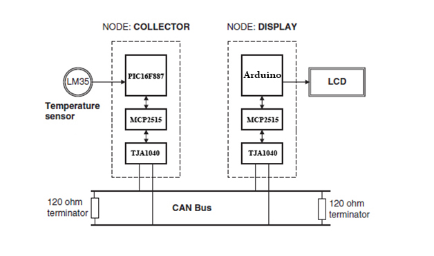
Fig. 1: Overview of Arduino and PIC Microcontroller Communication over CAN Interface
The DISPLAY Processor:
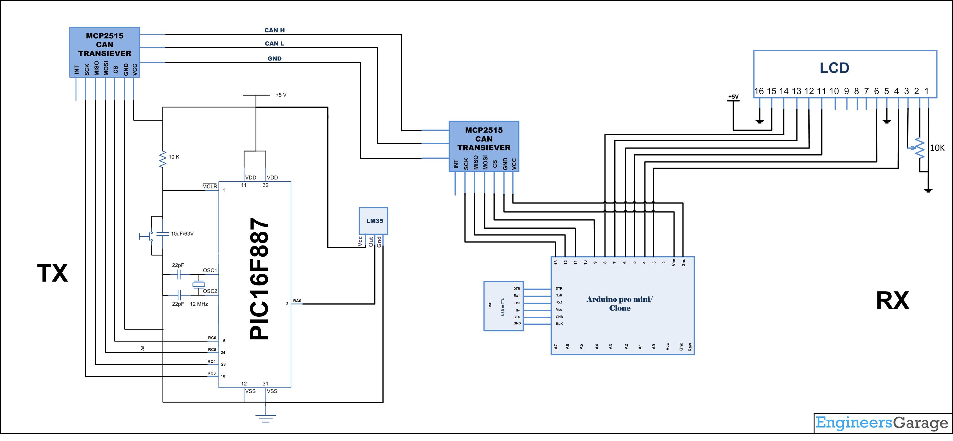
DISPLAY processor consists of an Arduino with a MCP2515 CAN module and an TJA1040 transceiver chip. The Microcontroller is operated from a 16MHz crystal. And MCP2515 has an SPI interface which is used to connect using SPI pins in Arduino. The Pins CANH and CANL of the transceiver chip are connected to the CAN bus. LCD is connected to Arduino to display the temperature values.
Receiving CAN data and Controlling Relays:
Load the program RX.ino after you save it onto your computer and open it in Arduino IDE .
-
Compile the program in the Arduino IDE
The following function is used to receive the values from the CAN bus and to display in an LCD. Detailed instruction can be found here.
CAN.readMsgBuf(&len, buf);
Loading software for Arduino:
If you are new to Arduino you can start with here. You have to start with the Arduino IDE (Integrated Development Environment) from Arduino . Download the code from below link and upload it to the Arduino board.
The COLLECTOR Processor:
The COLLECTOR processor consists of a PIC18F887 microcontroller with a MCP2515 CAN module and an TJA1040 transceiver chip. The PIC18F887 is operated from an 8MHz crystal. The MCLR input is connected to an external reset button. LM35DZ-type semiconductor temperature sensor is connected to Analog input AN0 of the Microcontroller. The sensor generates an analog voltage directly proportional to the measured temperature, the output is 10mV/C. For example, at 20 degree Celcius the output voltage is 200mV. The CANH and CANL outputs of this chip are connected directly to a twisted cable terminating at the CAN bus. The TJA1040is an 8-pin chip that supports data rates up to 1Mb/s. The chip can drive up to 112 nodes. A reference voltage equal to VDD/2 is output from pin 5 of the chip.
To change the speed of the MCP2515 Can Module in the collector side you can use the calculator software which is provided by MikroC. Download the file included in bottom to get the software.
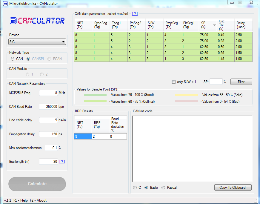
Fig. 2: Screenshot of CAN Calculations done for MCP2515 microcontroller on MikroC application
This is the format to change the speed of the MCP2515 can module,
CANInitialize (SJW, BRP, Phase_Seg1, Phase_Seg2, Prop_Seg, init_flag);
Here is the Initialisation made here to make it at 250Kbps
CANSPIInitialize (1,2,1,2,4,Can_Init_Flags);
For details about using MikroC to program pic controllers refer here.
The operation of the system is as follows:
-
The DISPLAY processor that waits for the current temperature message send from the COLLECTOR processor over the CAN bus.
-
The COLLECTOR processor measure the temperature, formats it, and sends to the DISPLAY processor over the CAN bus.
-
The DISPLAY processor reads the message from the CAN bus and then displays it on the LCD which is repeated every second.
Hardware assembly:
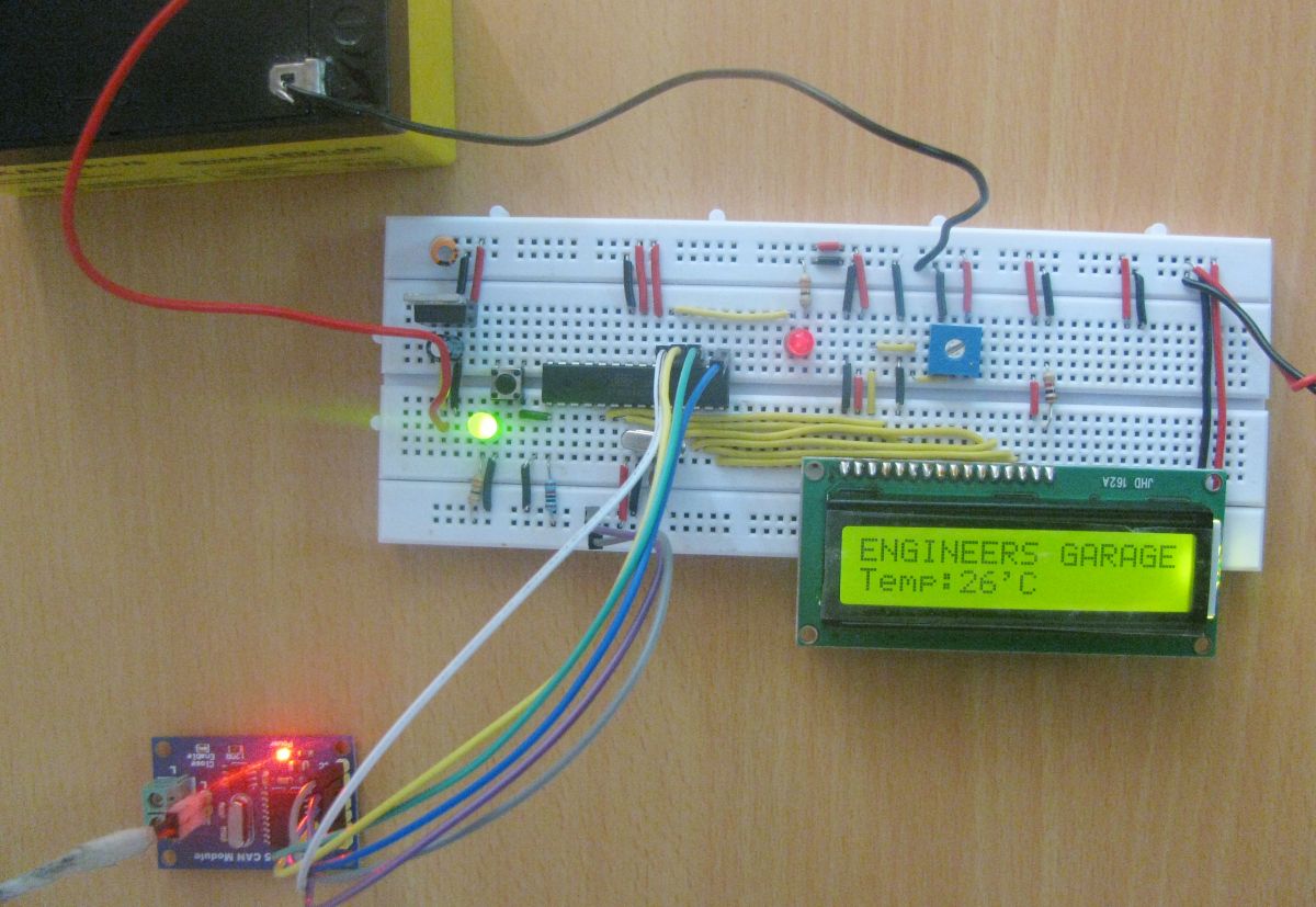
Fig. 3: Image showing Arduino based CAN Receiver Circuit
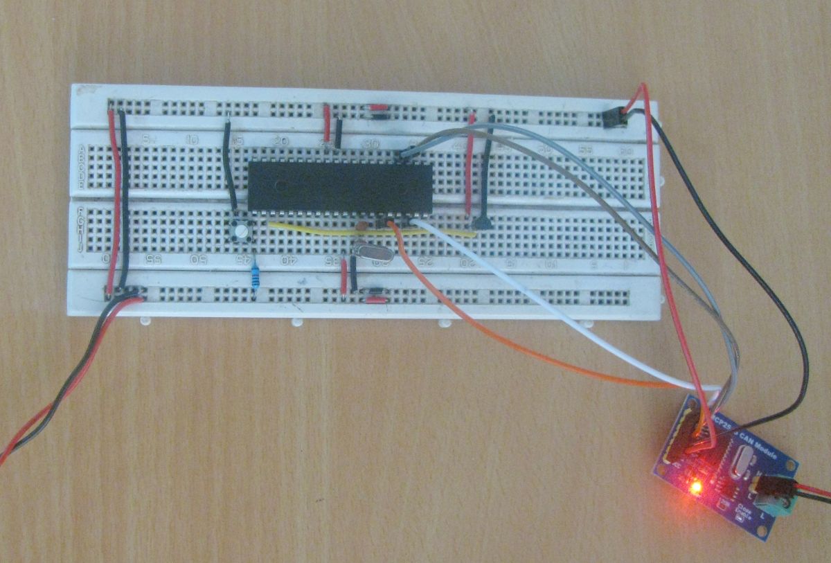
Fig. 4: Image showing PIC MCP2515 based CAN Transmitter Circuit
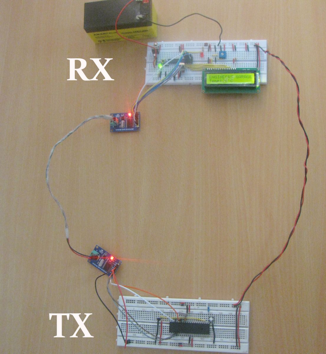
Fig. 5: Prototype of CAN Transmitter and Receiver circuits designed on Breadboards
Make the circuit as is given by the circuit diagram.
You may also like:
Project Source Code
Circuit Diagrams
Project Video
Filed Under: Arduino., Electronic Projects, PIC
Filed Under: Arduino., Electronic Projects, PIC




Questions related to this article?
👉Ask and discuss on Electro-Tech-Online.com and EDAboard.com forums.
Tell Us What You Think!!
You must be logged in to post a comment.