A home automation system allows controlling the home appliances from a remote control. The remote control can be a wireless remote or a mobile controlled remote system. In many home automation systems, instead of wireless control, the appliances are controlled by the remote station where keys or button directly interfaced to home automation circuit control switching of the appliances. In this project, similar control station with capacitive touch sensors is used to switch devices ON or OFF.
A capacitive touch sensor feeds back user input in the form of analog voltage to a microcontroller pin. The sensor works on the principle of capacitance. Any parallel plate capacitor has a capacitance given by the formulae –
C = εA/d
Where;
C is the capacitance
A is the area of plates
d is the distance between the plates
ε is the permittivity of the dielectric.
The capacitance is related to the voltage by the formulae –
C = Q/V
or V = Q/C
So as the distance between plates increases, capacitance decreases and Voltage between the plates increases.
A capacitive sensor can be made by a single metal plate connecting two terminals. The finger can serve as the other plate of the capacitor and air between the finger and the metal plate serves as the dielectric. The input voltage is supplied to one terminal and received at an input pin of the microcontroller from the other terminal. When the finger approaches the metal plate or physically touch the metal plate, the distance between the metal plate and the finger is reduced which decreases the capacitance and increases the voltage output at the receiving terminal.
The voltage input from the metal plate finger capacitor can be read at the microcontroller pin, digitized through ADC and compared to a reference value to operate it as a switch. This concept of capacitive touch is used to make touch or proximity sensors in the project which operate as control buttons. The use of capacitive sensors as buttons is utilized to drive relay circuit for switching the appliances.
The sensing of voltage from the capacitive sensors, control switching relay circuit and displaying a status of appliances is managed by an Arduino sketch running on Arduino UNO. The Arduino sketch is written on Arduino IDE and burnt to the board using AVR Dude.
Components Required –
1. Arduino UNO
2. 5 mm LED
3. 10K ohm PRESET
4. 7805 and 7812 voltage regulators.
5. 12V Relay.
6. 10K ohm PRESET
7. Transistor (BC547)
8. Bulb holder
9. TWO pin plug
Block Diagram –

Fig. 1: Block Diagram of Capacitive Touch Controlled Home Automation System
Circuit Connections –

Fig. 2: Prototype of Capacitive Touch Controlled Home Automation System
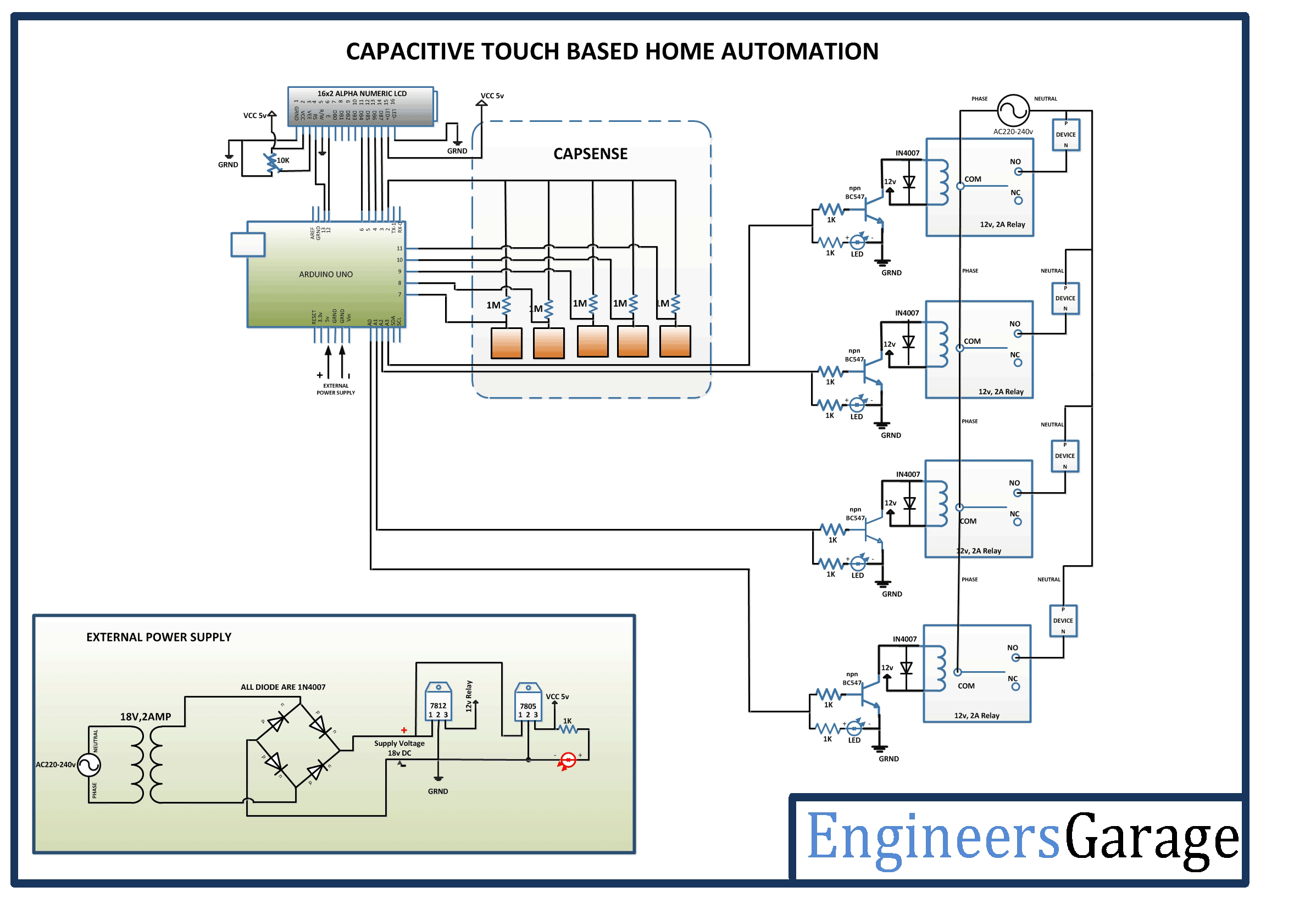
The Arduino board is the microcontroller board controlling the entire circuit. The capacitive touch sensors, LCD module, and relay circuits are connected to the Arduino board. These sensors, actuators, and modules are connected to the Arduino board in the following manner –
Power Supply – In the circuit, Arduino board and LCD module need a 5V regulated DC while relays need 12V regulated DC for their operation. The AC mains is used as the primary source of power. The supply from the mains is stepped down by a transformer and rectified by a full-bridge rectifier. The rectified output is regulated to 5V and 12V using 7805 and 7812 ICs. The pin 1 of both the voltage regulator ICs is connected to the anode of the battery and pin 2 of both ICs is connected to ground. The respective voltage outputs are drawn from pin 3 of the respective voltage regulator ICs. A LED along with a 10K Ω pull-up resistor is also connected between common ground and output pin to get a visual hint of supply continuity.
16X2 LCD: The 16X2 LCD display will be used to display the status of devices. It is connected to the Arduino board by connecting its data pins to pins 3 to 6 of the Arduino board. The RS and E pins of the LCD are connected to pins 13 and 12 of the Arduino UNO respectively. The RW pin of the LCD is grounded.

Fig. 3: Table listing circuit connections between Arduino Uno and Character LCD
The standard open-source library for interfacing LCD with Arduino UNO is used in the project. The library works as expected and needs no changes or modifications.
Relays – The 12V 2A relays are used to switch the AC appliances ON or OFF in the project. The relays are connected to the pins A0, A1, A2 and A3 of Arduino board via BC547 transistor circuits connected in a common emitter configuration. The phase wire from the AC supply is provided at the COM terminal of the relays. When a HIGH logic is received at the interfaced microcontroller pins, the COM point switches from NC to NO point where a relay short-circuits the phase with the neutral wire switching the supply to the appliance ON. The LEDs are connected parallel to the relay circuit with pull-up resistors in series. These LEDs give the visual hint of the ON/OFF status of appliances.

Fig. 4: Circuit Diagram of Relay Driver
Capacitive Sensors – The capacitive sensors are built using five metal plates. One terminal from each metal plate is connected to the pin 2 of the Arduino board. The other terminals from the capacitive plates are connected to pins 7, 8, 9, 10 and 11 of the Arduino. These pins serve to sense voltage from the capacitive sensors. A sensitivity resistor of 1M Ω is connected in series to the common terminal. The resistor provides the voltage at the plate. The higher is the value of this resistance higher is the sensitivity. During testing of the project, it was found that 1M Ω of the resistor on keeping a reference voltage at half of the ADC channel width switches the device on touching the plate. A 10M Ω resistor on keeping a reference voltage at half of the ADC channel width switches the device from 4 to 6 inches distance and a 40M Ω resistor on keeping a reference voltage at half of the ADC channel width switches the device from 12 to 24 inches distance.

Fig. 5: Circuit Diagram of Capacitive Touch Sensor
The sensors connected to pins 7, 8, 10 and 11 control the appliances interfaced through relay circuit to pins A0, A1, A2 and A3 of the Arduino. The sensor connected to pin 9 of the board controls switching off all appliances together.
How the circuit works –
When the circuit is powered on, the Arduino loads the required libraries. Fortunately, Arduino has a standard library for handling capacitive sensors. The Arduino code set the pins connected to the relays to LOW logic switching the appliances OFF initially. The status of the appliances is updated on the LCD display. The Arduino board waits for the touch on the capacitive sensors.
When a capacitive sensor is not touched, the sensor has no effective capacitance and the voltage dropped at the sensitivity resistor has no effect at the other terminal of the sensor. When the sensor is touched by a finger, there is an effective capacitance of the sensor and a voltage is induced at the output terminal of the sensor due to this capacitance. The voltage is read by the microcontroller pin and converted to a digitized reading. The Arduino UNO has 10-bit ADC channel, that is why the digitized reading has a maximum value of thousand. The reference value for comparison of the voltage is taken 500.
The Arduino code detects the touch by comparing voltage reading with the reference value and traces the status of each device by a set of variables. On tapping a sensor, the respective device is toggled from either ON state to the OFF state if it is ON or from OFF state to ON state if it is OFF. The Arduino board set the logic at the respective pin connecting the device through relay circuit to HIGH for switching the device ON and set the logic at the respective pin to LOW for switching the device OFF.
When a HIGH logic is passed to a pin connecting the relay circuit, it triggers the base of the switching transistor and current starts flowing from the collector to the emitter so the collector becomes ground. As the collector gets ground, one of the terminals of the respective relay also gets grounded and relay switches the connector from NC to NO point switching the device ON.
When the sensors connected to pins 7, 8, 10 and 11 of the Arduino are touched, the status of devices connected to pins A0, A1, A2 and A3 respectively is toggled. When the sensor connected to pin 9 of the Arduino is touched, the status of all the devices is toggled.
Programming Guide –
The Arduino code loads the CapacitiveSensor.h to handle capacitive sensors and LiquidCrystal.h for interfacing LCD display. Five objects of capacitive sensor type are instantiated with mapping to the connected pins using CapacitiveSensor() method in which first parameter determines the sensitivity resistance and second parameter determines the pin connecting sensor. An object of LCD type is instantiated and assigned the connected pins. A set of variables to hold voltage levels at the capacitive sensors is declared followed by a set of variables holding the status of devices. A variable to hold the reference voltage level is declared.
#include <CapacitiveSensor.h>
#include <LiquidCrystal.h>
CapacitiveSensor cs1 = CapacitiveSensor(2,7); // 10M resistor between pins 4 & 2, pin 2 is sensor pin, add a wire and or foil if desired
CapacitiveSensor cs2 = CapacitiveSensor(2,8); // 10M resistor between pins 4 & 2, pin 2 is sensor pin, add a wire and or foil if desired
CapacitiveSensor cs3 = CapacitiveSensor(2,9); // 10M resistor between pins 4 & 2, pin 2 is sensor pin, add a wire and or foil if desired
CapacitiveSensor cs4 = CapacitiveSensor(2,10); // 10M resistor between pins 4 & 2, pin 2 is sensor pin, add a wire and or foil if desired
CapacitiveSensor cs5 = CapacitiveSensor(2,11); // 10M resistor between pins 4 & 2, pin 2 is sensor pin, add a wire and or foil if desired
LiquidCrystal lcd(13,12,6,5,4,3);// Pins used for RS,E,D4,D5,D6,D7
long cs1v,cs2v,cs3v,cs4v,cs5v;
int a=0,b=0,c=0,d=0,e=0;
int touchref = 500;
The baud rate for serial communication with the LCD module is set to 9600 bits per second using begin() method on Serial class and the pins connecting the relays are set to digital output using pinMode() function. The pins connected to the relays are initially set to LOW logic setting the devices to OFF status. Some initial messages are flashed on the LCD display and the status of the devices is updated on the LCD display.
void setup()
{
Serial.begin(9600);
pinMode(A0,OUTPUT);
pinMode(A1,OUTPUT);
pinMode(A2,OUTPUT);
pinMode(A3,OUTPUT);
digitalWrite(A0,LOW);
digitalWrite(A1,LOW);
digitalWrite(A2,LOW);
digitalWrite(A3,LOW);
lcd.begin(16,2);
lcd.setCursor(0,0); //Initially set the cursor position of LCD to 1st Columb 1st row.
lcd.print(“Engineers Garage”);//After initialising print data
lcd.setCursor(0,1); //Initially set the cursor position of LCD to 1st Columb 2nd row.
lcd.print(” “); //print blank to clear all the data on LCD
delay(3000);
lcd.setCursor(0,0);
lcd.print(” CT Based Home “);
lcd.setCursor(0,1);
lcd.print(” Automation “);
delay(3000);
lcd.setCursor(0,0);
lcd.print(“D1:OFF D2:OFF”); //Initially dispaly all are OFF
lcd.setCursor(0,1);
lcd.print(“D3:OFF D4:OFF”);//Initially dispaly all are OFF
}
The loop() function is called in which the voltage level from the capacitive sensors is read and stored in variables declared for it using the capacitiveSensor() method with a number of samples passed as a parameter. The value of the sensor is compared with reference voltage level along with the status of the variable indicating the ON or OFF status of the respective device and the pin connecting the respective relay is set to HIGH or LOW depending upon the current status of device. If device if OFF, the respective pin is set HIGH and respective device status variable is set to 1. The current status of the device is updated on the LCD. If the device is ON, the respective pin is set LOW and respective device status variable is set to 0. The current status of the device is updated on the LCD. On tapping the sensor connected at pin 9 represented in the code by variable cs3, the status of all the devices is set to ON or OFF together.
The complete code for the Capacitive Touch Controlled Home Automation System can be found in the code section.
Project Source Code
###
//Program to #include <CapacitiveSensor.h> #include <LiquidCrystal.h> CapacitiveSensor cs1 = CapacitiveSensor(2,7); // 10M resistor between pins 4 & 2, pin 2 is sensor pin, add a wire and or foil if desired CapacitiveSensor cs2 = CapacitiveSensor(2,8); // 10M resistor between pins 4 & 2, pin 2 is sensor pin, add a wire and or foil if desired CapacitiveSensor cs3 = CapacitiveSensor(2,9); // 10M resistor between pins 4 & 2, pin 2 is sensor pin, add a wire and or foil if desired CapacitiveSensor cs4 = CapacitiveSensor(2,10); // 10M resistor between pins 4 & 2, pin 2 is sensor pin, add a wire and or foil if desired CapacitiveSensor cs5 = CapacitiveSensor(2,11); // 10M resistor between pins 4 & 2, pin 2 is sensor pin, add a wire and or foil if desired LiquidCrystal lcd(13,12,6,5,4,3);// Pins used for RS,E,D4,D5,D6,D7 long cs1v,cs2v,cs3v,cs4v,cs5v; int a=0,b=0,c=0,d=0,e=0; int touchref = 500; void setup() { Serial.begin(9600); pinMode(A0,OUTPUT); pinMode(A1,OUTPUT); pinMode(A2,OUTPUT); pinMode(A3,OUTPUT); digitalWrite(A0,LOW); digitalWrite(A1,LOW); digitalWrite(A2,LOW); digitalWrite(A3,LOW); lcd.begin(16,2); lcd.setCursor(0,0); //Initially set the cursor position of LCD to 1st Columb 1st row. lcd.print("Engineers Garage");//After initialising print data lcd.setCursor(0,1); //Initially set the cursor position of LCD to 1st Columb 2nd row. lcd.print(" "); //print blank to clear all the data on LCD delay(3000); lcd.setCursor(0,0); lcd.print(" CT Based Home "); lcd.setCursor(0,1); lcd.print(" Automation "); delay(3000); lcd.setCursor(0,0); lcd.print("D1:OFF D2:OFF"); //Initially dispaly all are OFF lcd.setCursor(0,1); lcd.print("D3:OFF D4:OFF");//Initially dispaly all are OFF } void loop() { cs1v = cs1.capacitiveSensor(30); cs2v = cs2.capacitiveSensor(30); cs3v = cs3.capacitiveSensor(30); cs4v = cs4.capacitiveSensor(30); cs5v = cs5.capacitiveSensor(30); if(cs1v>touchref && a==0){ digitalWrite(A0,HIGH); a=1; lcd.setCursor(3,0); lcd.print("ON "); delay(200); } else if(cs1v>touchref && a==1){ digitalWrite(A0,LOW); a=0; lcd.setCursor(3,0); lcd.print("OFF"); delay(200); } if(cs2v>touchref && b==1){ digitalWrite(A1,HIGH); b=0; lcd.setCursor(13,0); lcd.print("ON "); delay(200); } else if(cs2v>touchref && b==0){ digitalWrite(A1,LOW); b=1; lcd.setCursor(13,0); lcd.print("OFF "); delay(200); } if(cs3v>touchref && c==1){ digitalWrite(A0,LOW); digitalWrite(A1,LOW); digitalWrite(A2,LOW); digitalWrite(A3,LOW); lcd.setCursor(0,0); lcd.print("D1:OFF D2:OFF"); //Initially dispaly all are OFF lcd.setCursor(0,1); lcd.print("D3:OFF D4:OFF"); a=0; b=0; c=0; d=0; e=0; delay(200); } else if(cs3v>touchref && c==0){ digitalWrite(A0,HIGH); digitalWrite(A1,HIGH); digitalWrite(A2,HIGH); digitalWrite(A3,HIGH); lcd.setCursor(0,0); lcd.print("D1:ON D2:ON "); //Initially dispaly all are OFF lcd.setCursor(0,1); lcd.print("D3:ON D4:ON ");//Initially dispaly all are OFF a=0; b=0; c=1; d=0; e=0; delay(200); } if(cs4v>touchref && d==1){ digitalWrite(A2,HIGH); d=0; lcd.setCursor(3,1); lcd.print("ON "); delay(200); } else if(cs4v>touchref && d==0){ digitalWrite(A2,LOW); d=1; lcd.setCursor(3,1); lcd.print("OFF "); delay(200); } if(cs5v>touchref && e==1){ digitalWrite(A3,HIGH); e=0; lcd.setCursor(13,1); lcd.print("ON "); delay(200); } else if(cs5v>touchref && e==0){ digitalWrite(A3,LOW); e=1; lcd.setCursor(13,1); lcd.print("OFF "); delay(200); } delay(25);// arbitrary delay to limit data to serial port }###
Circuit Diagrams
Project Video
Filed Under: Electronic Projects
Filed Under: Electronic Projects

Questions related to this article?
👉Ask and discuss on EDAboard.com and Electro-Tech-Online.com forums.
Tell Us What You Think!!
You must be logged in to post a comment.