Robotic cars are commonly used for outdoor operations. These are designed for different purposes and applications. These robotic vehicles are meant to move over a surface and reach a spot to carry out the intended application or perform specific tasks. The robotic cars can be controlled with a remote control which may be connected to the robot either through a wired connection or a wireless interface. The wireless connectivity is usually provided by Wi-Fi, Bluetooth, RF or mobile networks. One of the RF technologies available for providing wireless connection is Zigbee.
Zig Bee is a standard wireless communication technology that transfers data over ISM radio bands. It operates on 2.4 GHz worldwide and at other ISM frequencies in select countries. The communication protocol is commonly used for making personal area networks for applications like home automation, wireless office networks and sensor based data networks. The Zig-Bee modules are commonly used for connecting low power embedded devices that need to operate in a small area at low data rates. A Zig-Bee module operating on 2.4 GHz band has the data rate of 250 Kbps. X-bee is a Zigbee module from Digi International. In this project a wireless robot is designed which connects with the remote control using X-Bee module.
The remote control has capacitive sensors to feed input by the user instead of typical push buttons. The capacitive sensors are touch based sensors which use capacitance to detect touch of the user. Being touch sensitive, these sensors are fast responsive and allow controlling the robot more precisely and quickly. Due to touch sensitivity the response time in controlling the robot by a human operator is considerably reduced. The capacitive sensors in the remote control for this project are used to move the robot in forward, backward, left or right direction or to stop the robot. So the capacitive touch sensor takes input from the user for controlling the navigation of the robot.
A capacitive touch sensor feeds back user input in the form of analog voltage to a microcontroller pin. The sensor works on the principle of capacitance. Any parallel plate capacitor has a capacitance given by the formulae –
C = εA/d
Where;
C is the capacitance
A is the area of plates
d is the distance between the plates
ε is the permittivity of the dielectric.
The capacitance is related to the voltage by the formulae –
C = Q/V
or V = Q/C
So as the distance between plates increases, capacitance decreases and Voltage between the plates increases. A capacitive sensor can be made by a single metal plate connecting two terminals. The finger of the user serves as the other plate of the capacitor and air between the finger and the metal plate serves as the dielectric. The input voltage is supplied to one terminal and received at an input pin of the microcontroller from the other terminal. When the finger approaches the metal plate or physically touch the metal plate, the distance between the metal plate and the finger is reduced which decreases the capacitance and increases the voltage output at the receiving terminal.
The voltage input from the metal plate – finger capacitor can be read at the microcontroller pin, digitized through ADC and compared to a reference value to operate it as a switch. This concept of capacitive touch is used to make touch or proximity sensors in the project which operate as control buttons.
The capacitive sensors are used on the remote control. The remote is connected with the robot using Zigbee wireless technology for which two X-bee modules are used. So, there are two circuits – one is remote circuit and the other is receiver circuit mounted on the robot. The robot is built using two-wheel and a castor body and the DC motors attached to the wheels is controlled using L293D motor driver IC.

Fig. 1: Prototype of XBee based Capacitive Touch controlled Robot
Components Required –

Fig. 2: List of components required for XBee based Capacitive Touch controlled Robot
Block Diagram –
The remote circuit has the following block diagram –

Fig. 3: Block Diagram of Capacitive Touch Remote Circuit of XBee based Arduino Robot
The receiver circuit mounted on the robot has the following block diagram –

Fig. 4: Block Diagram of XBee based Capacitive Touch controlled Robot
Circuit Connections –
There are two circuits that make up this project – one is remote circuit built using Arduino UNO, capacitive sensors and X-Bee module. The other one is receiver circuit mounted on robot built using Arduino UNO, X-bee module and L293D motor driver IC.
The remote circuitry is built using the following components –

Fig. 5: Image of Capacitive Touch Remote Circuit for XBee based Arduino Robot
Arduino UNO – Arduino UNO is one of the most popular prototyping boards. It is used frequently in robotic applications as it is small in size and packed with rich features. The board comes with built-in Arduino boot loader. It is an Atmega 328 based controller board which has 14 GPIO pins, 6 PWM pins, 6 Analog inputs and on board UART, SPI and TWI interfaces. In this remote circuit, 8 pins of the board are utilized. There are six pins used to interface the capacitive sensors. Of these five pins are used as analog input pins. The two pins RX and TX of the board are used to interface the X-bee module and establish serial communication over USART. Learn more about Arduino UNO from here.
X-Bee module – X-Bee is a Zigbee module from Digi international. Zigbee is a wireless communication module which use IEEE 802.15.4 standard. The 802.15.4 is a IEEE standard for low power applications of radio frequency. It used in many products for wireless communication functionality. It can be used as a transmitter and receiver both. It uses serial communication to send and receive data. It has two series, series 1 and series 2. Series 1 is comparatively easy to use and it is recommended for beginners. In this project Series 1 X-bee module is used. The Series 1 Zigbee module cannot work in mesh network. That means it cannot talk to more than one Zigbee at a time. Learn more about Zigbee technology.
The series 1 X-bee is a 20-pin module with the following pin configuration –

Fig. 6: Table listiing pin configuration of Xbee Series-1 Module
The module can be connected with a controller board using UART. The module can be connected with the Arduino by connecting its DOUT (UART Data Out) or TX pin with RX pin of the Arduino and DIN (UART Data In) or RX pin with the TX pin of the Arduino. The VCC and Ground pins of the module must be connected to common VCC and ground. The X-Bee module used in the remote circuit is configured to work as RF data transmitter.
Capacitive Sensors – The capacitive sensors are built using five metal plates. One terminal from each metal plate is connected to the pin 2 of the Arduino board. The other terminals from the capacitive plates are connected to pins 7, 8, 9, 10 and 11 of the Arduino. These pins serve to sense voltage from the capacitive sensors. A sensitivity resistor of 1M Ω is connected in series at the common terminal from each plate. The resistor provides the voltage at the plate. The higher is the value of this resistance higher is the sensitivity. During testing of the sensors, it was found that on connecting 1M Ω of resistor and keeping a reference voltage at half of the ADC channel width, the sensor was responding to the touch of the finger. On connecting 10M Ω resistor and keeping a reference voltage at half of the ADC channel width, the sensor was responding from 4 to 6 inches distance and on connecting a 40M Ω resistor and keeping a reference voltage at half of the ADC channel width, the sensor was responding from 12 to 24 inches distance.

Fig. 7: Circuit Diagram of Capacitive Touch Sensor
The sensors connected at pins 7, 8, 9, 10 and 11 of the Arduino control the movement of robot in forward, backward, left and right direction and to stop the robot respectively.
Power Supply – All the components of the remote circuit requires a 5V DC supply. The Arduino board is powered with 5V by a USB cable. The voltage input for X-bee module is drawn from 5V Vout pin of Arduino. The voltage for operation of the capacitive sensors is provided by the pin 2 (pin common connected to the sensors) of the Arduino.
The receiver circuit mounted on the robot consist of the following components –

Fig. 8: Image of XBee based Capacitive Touch controlled Robot
Arduino UNO – The receiver circuit also uses Arduino UNO as the controller board. The Arduino used in the receiver circuit has 6 pins utilized. The GPIO pins of this Arduino are used to interface the L293D motor driver IC. These pins are connected with the input pins of the motor driver IC. The two pins of the Arduino are used to interface the X-Bee Series 1 module.
X-Bee module – The X-Bee module used on the receiver circuit is configured to work as RF data receiver. The module is interfaced with the Arduino by connecting its DOUT (UART Data Out) or TX pin with RX pin of the Arduino and DIN (UART Data In) or RX pin with the TX pin of the Arduino. The VCC and Ground pins of the module must be connected to common VCC and ground.
L293D motor Driver IC – The L293D is a dual H-bridge motor driver integrated circuit (IC). The Motor drivers act as current amplifiers since they take a low-current control signal and provide a higher-current signal. This higher current signal is used to drive the motors. It has 16 pins with following pin configuration:

Fig. 9: Table listing pin configuration of L293D Motor Driver IC
There are two DC motors used for making the robotic car. The DC motors are interfaced between pins 3 and 6 and pins 14 and 11 of the motor driver IC.
The L293D IC controls the DC Motors according to the following truth tables:

Fig. 10: Truth Table of L293D Motor Driver IC
The pin 4, 5, 13 and 12 of the L293D are grounded while pin 1, 16 and 9 are connected to 5V DC and pin 8 is connected to 12V DC. The pins 15, 2, 7 and 10 of the motor driver IC are connected to pins 5, 2, 3 and 4 of the Arduino board. The DC motor attached to right wheel is connected to pins 11 and 14 while motor attached to left wheel is connected to pins 3 and 6 of the motor driver IC. The enable pins of the IC (pins 1 and 9) are hard wired to the 5V DC supply.
Geared DC Motors – In this robot, 12V geared DC motors are attached to the wheels. Geared DC motors are available with wide range of RPM and Torque, which allow a robot to move based on the control signal it receives from the motor driver IC.
Power Supply – The Arduino UNO, X-Bee module and logic supply pins of the motor driver IC requires 5V DC while the supply pin of the driver IC requires 12V DC. A 12V NIMH battery is used as the primary source of power. The supply from the battery is regulated to 5V and 12V using 7805 and 7812 ICs. The pin 1 of both the voltage regulator ICs is connected to the anode of the battery and pin 2 of both ICs is connected to ground. The respective voltage outputs are drawn from pin 3 of the respective voltage regulator ICs. An LED along with a 10K Ω pull-up resistor is also connected between common ground and output pin to get a visual hint of supply continuity. Despite using 12V battery, 7812 is used to provide a regulated and stable supply to the motor driver IC.
How the circuit works –
The wireless robot is powered by a battery and once the battery is attached in the control circuitry of the robot it starts operating. As it is powered, the X-Bee module interfaced in the receiver circuit is configured as RF data receiver and starts waiting for commands from the remote control. The commands are passed in the form of single character strings by the remote control. The following strings are passed by the remote circuit to the receiver circuit for moving the robot in forward, backward, left and right direction and stopping the robot –

Fig. 11: Table listing command strings for controlling Wireless Arduino Robot
The command strings are read by the Arduino board using UART port. On receiving a command, the Arduino board compares it with the command strings mentioned above and change digital logic at the pins connected to the input pins of the motor driver IC to perform the desired operation. The robot is moved forward, backward, left or right by implementing the following input logic at the motor driver pins –

Fig. 12: Logic Table of L293D Motor Driver IC for Wireless Arduino Robot
The input pins of the motor driver IC are connected to the Arduino pins and by changing the digital logic at the Arduino pins, respective logic is implemented at the input pins of the motor driver IC.
The remote circuit has capacitive sensors to get user input by touch. When a capacitive sensor is not touched, the sensor has no effective capacitance and the voltage dropped at the sensitivity resistor has no effect at the other terminal of the sensor. When the sensor is touched by a finger, there is an effective capacitance across the sensor and a voltage is induced at the output terminal of the sensor due to this capacitance. The voltage is read by the microcontroller pin and converted to a digitized reading. The Arduino UNO has 10-bit ADC channel, that is why, the digitized reading has a maximum value of 1023. The reference value for comparison of the voltage is taken 900.
On detecting touch at a capacitive sensor, command strings are passed serially by the Arduino to the X-Bee module. The capacitive sensors are connected to the following Arduino pins and have following command strings and intended operations associated with them –

Fig. 13: Table listing circuit connections between Arduino and Capacitive Touch Sensor Keypad
For activating the wireless connection between the robot and the remote circuit, it is important to configure the X-Bee modules on both sides. The CoolTerm terminal application is used to configure the X-Bee modules. In order to make PC to communicate directly with the Xbee, even arduino board can be used by removing the controller IC or an simple sketch can be uploaded to the arduino boards, which makes Xbee enabled to directly communicate with computer and not to the Arduino board. First of the circuit connections between the X-Bee module and the Arduino must be made as mentioned above.
Now follow the following steps –
Open the CoolTerm application and navigate to connection -> options -> serial port and select the COM port. Set the baud rate and go to Terminal option and select the Local echo check box to display what typed commands and click OK to save changes.

Fig. 14: Screenshot of CoolTerm Application
To configure X-Bee, the following AT commands should be used.
First make the X-Bee to enter into a command mode by entering +++ in the terminal, once it gets OK then follow with the other AT commands
First off, XBEE radios only operate at a given baud rate, this is the number of bits per second that the X-Bee can send. A brand new X-Bee has default baud rate of 9600 bps, which is quite slow. The baud rate can be changed by altering the ATBD register. Both of the X-Bee modules must have the same baud rate to talk to one another. The available baud rates (and corresponding ATBD value) are as follow –

Fig. 15: Table listing ATBD values for different baud rates of Xbee Module
So, to set the baud rate at 9600, the following command should be passed –
ATBD3
The next important parameter is the Personal Area Network ID. This is a number shared amongst each XBEE in a network. Here, there are only 2 X-Bee modules, but there can be many X-Bee modules in a network (for which Series 2 X-Bee modules should be used). The X-Bee modules on different networks do not “see” each other. The default PAN is 3332, so avoid using that number. The PAN ID is stored in ATID register. The register can be altered by passing the following command –
ATID1001
Once both of the X-Bee modules are on the same network, each one of them must be given an address number denoted by ATMY register. The destination address can also be set, which is what address number has to talk to and is denoted by ATDL register (for destination low, there is no need to use the high bytes if the address numbers are less than 16 bits in length). A sample setup of two X-Bee modules that will talk directly to one another at 38.4 kbps can be done by passing the following commands –
ATMY10
ATDL11
So, both X-Bee modules are configured by passing the following AT commands –
X-BEE module 1:
ATID1001
ATMY10
ATDL11
ATBD3
X-BEE module 2:
ATID1001
ATMY11
ATDL10
ATBD3
An important thing to note though is that changes made are stored in temporary memory. if X-Bee modules are powered off, the configurations are lost. Send ATWR to write the changes to non-volatile memory, so that they are not lost while power off.

Fig. 16: Screenshot of AT commands for Xbee Module from CoolTerm Application
Once the X-Bee modules are configured, the Arduino sketch for the remote circuit and receiver circuit can be uploaded at the respective controller board.

Fig. 17: Image of XBee based Capacitive Touch controlled Wireless Arduino Robot
Check the Arduino Sketch uploaded on Arduino connected in the remote circuit to see how Arduino detects touch by cap sense using capacitive sensor library and uses sensor reading to send command strings serially to the X-bee module. Check the Arduino Sketch uploaded on Arduino connected in the receiver circuit to see how command strings are read through X-Bee module and motor driver IC is controlled according to the commands received.
Programming Guide –
Remote Circuit Program: The Arduino code loads the CapacitiveSensor.h to handle capacitive sensors. Five objects of capacitive sensor type are instantiated with mapping to the connected pins using CapacitiveSensor() method in which first parameter determines the sensitivity resistance and second parameter determines the pin connecting sensor. A set of variables to hold voltage levels at the capacitive sensors is declared followed by a set of variables holding the status of devices. A variable to hold the reference voltage level is declared. The baud rate for serial communication with the X-bee module is set to 9600 bits per second using begin() method on Serial class.

Fig. 18: Screenshot of initialization in Arduino Code on Transmitter Side of Wireless Robot
The loop() function is called in which the voltage level from the capacitive sensors is read and stored in variables declared for it using the capacitiveSensor() method with a number of samples passed as a parameter. With the voltage value compared with the reference value following the condition and the respective data is sent to the X-bee using pritln() function.

Fig. 19: Screenshot of loop function in Arduino Code on Transmitter Side of Wireless Robot
Receiver Circuit Program: – At the receiver side coding, the character variable is initialized to store the receiving data. The motor pins are defined which are connected between the arduino and motor driver IC. In the setup() function, begin() function is used to set the baud rate to 9600 to receive the serial data from X-bee. The Arduino pins connected to input pins of the motor driver IC are configured to digital output using pinMode function.

Fig. 20: Screenshot of initialization in Arduino Code on Receiver Side of Wireless Robot
The loop() function is called in which it continuously checks for the incoming serial data, if serial data is available, the data is read using serial.read() function and stored in the variable. Then stored data is checked with the condition mentioned. Then with respect to conditions function call for robot movement is carried out.

Fig. 21: Screenshot of loop function in Arduino Code on Receiver Side of Wireless Robot
The move_forward() function is called to move robot in forward direction. The move_backward() function is called to move robot in backward direction. The turn_left() function is used to turn the robot in left direction and turn_right() function is used to turn the robot in right direction. The robo_stop() function is used to stop the robot.
Check out the complete Arduino codes and quickly get hands dirty with an Arduino IDE. It will be fun making this robot.
You may also like:


Project Source Code
###
//Program to char msg = ' '; //definining the arduino pin number for arduino #define L_motor1 2 #define L_motor2 3 #define R_motor1 4 #define R_motor2 5 //function prototype void move_forward(); void move_backward(); void turn_right(); void turn_left(); void setup() { //For enabling serial data transfer at rate of 9600 Serial.begin(9600); //pin modes of motor conected with arduino pinMode(L_motor1, OUTPUT); pinMode(L_motor2, OUTPUT); pinMode(R_motor1, OUTPUT); pinMode(R_motor2, OUTPUT); digitalWrite(L_motor1, LOW); digitalWrite(L_motor2, LOW); digitalWrite(R_motor1, LOW); digitalWrite(R_motor2, LOW); } void loop() { //checking for serial data receiving if(Serial.available() > 0) { //if reading the serial data msg = Serial.read(); //with respect to the data received controlling the direction of motor if(msg == 'R') { turn_right(); } if(msg == 'L') { turn_left(); } if(msg == 'F') { move_forward(); } if(msg == 'B') { move_backward(); } if(msg == 'S') { robo_stop(); } } delay(80); } void move_forward() { digitalWrite(L_motor1, HIGH); digitalWrite(L_motor2, LOW); digitalWrite(R_motor1, HIGH); digitalWrite(R_motor2, LOW); } void move_backward() { digitalWrite(L_motor1, LOW); digitalWrite(L_motor2, HIGH); digitalWrite(R_motor1, LOW); digitalWrite(R_motor2, HIGH); } void turn_left() { digitalWrite(L_motor1, LOW); digitalWrite(L_motor2, LOW); digitalWrite(R_motor1, HIGH); digitalWrite(R_motor2, LOW); } void turn_right() { digitalWrite(L_motor1, HIGH); digitalWrite(L_motor2, LOW); digitalWrite(R_motor1, LOW); digitalWrite(R_motor2, LOW); } void robo_stop() { digitalWrite(L_motor1, LOW); digitalWrite(L_motor2, LOW); digitalWrite(R_motor1, LOW); digitalWrite(R_motor2, LOW); }###
Circuit Diagrams
| Circuit-Diagram-Capacitive-Touch-Sensor-Keypad-Wireless-Robot | 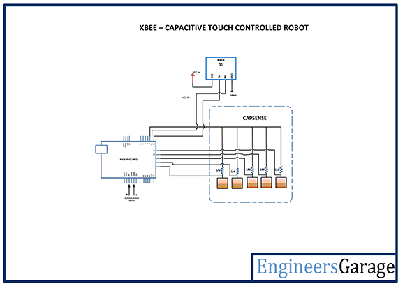 |
| Circuit-Diagram-XBee-Capacitive-Touch-Controlled-Robot | 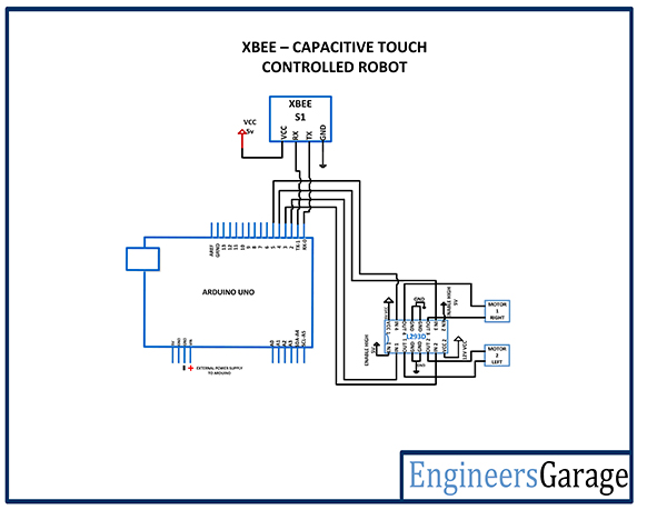 |
Project Video
Filed Under: Electronic Projects, Featured Contributions
Filed Under: Electronic Projects, Featured Contributions

Questions related to this article?
👉Ask and discuss on EDAboard.com and Electro-Tech-Online.com forums.
Tell Us What You Think!!
You must be logged in to post a comment.