Engineers Garage

  • Electronic Projects & Tutorials
    • Electronic Projects
      • Arduino Projects
      • AVR
      • Raspberry pi
      • ESP8266
      • BeagleBone
      • 8051 Microcontroller
      • ARM
      • PIC Microcontroller
      • STM32
    • Tutorials
      • Audio Electronics
      • Battery Management
      • Brainwave
      • Electric Vehicles
      • EMI/EMC/RFI
      • Hardware Filters
      • IoT tutorials
      • Power Tutorials
      • Python
      • Sensors
      • USB
      • VHDL
    • Circuit Design
    • Project Videos
    • Components
  • Articles
    • Tech Articles
    • Insight
    • Invention Stories
    • How to
    • What Is
  • News
    • Electronic Product News
    • Business News
    • Company/Start-up News
    • DIY Reviews
    • Guest Post
  • Forums
    • EDABoard.com
    • Electro-Tech-Online
    • EG Forum Archive
  • DigiKey Store
    • Cables, Wires
    • Connectors, Interconnect
    • Discrete
    • Electromechanical
    • Embedded Computers
    • Enclosures, Hardware, Office
    • Integrated Circuits (ICs)
    • Isolators
    • LED/Optoelectronics
    • Passive
    • Power, Circuit Protection
    • Programmers
    • RF, Wireless
    • Semiconductors
    • Sensors, Transducers
    • Test Products
    • Tools
  • Learn
    • eBooks/Tech Tips
    • Design Guides
    • Learning Center
    • Tech Toolboxes
    • Webinars & Digital Events
  • Resources
    • Digital Issues
    • EE Training Days
    • LEAP Awards
    • Podcasts
    • Webinars / Digital Events
    • White Papers
    • Engineering Diversity & Inclusion
    • DesignFast
  • Guest Post Guidelines
  • Advertise
  • Subscribe

Capacitor : Types of Capacitors

By Nikhil Agnihotri June 28, 2011

What is a Capacitor?

A capacitor is a passive two terminal component which stores electric charge. This component consists of two conductors which are separated by a dielectric medium. The potential difference when applied across the conductors polarizes the dipole ions to store the charge in the dielectric medium. The circuit symbol of a capacitor is shown below:

Symbol of a capacitor

Fig. 1: Symbol of a capacitor

The capacitance or the potential storage by the capacitor is measured in Farads which is symbolized as ‘F’. One Farad is the capacitance when one coulomb of electric charge is stored in the conductor on the application of one volt potential difference.
The charge stored in a capacitor is given by 
Q = CV
Where Q – charge stored by the capacitor
            C – Capacitance value of the capacitor
            V – Voltage applied across the capacitor
Note the other formula of current, I = dQ/dt
Taking the derivative with respect to time,
dQ/dt = d(CV)/dt
From the above statement, we can express the equation as
I = C (dV/dt)

As you turn on the power supply, the current begins to flow through the capacitor inducing the positive and negative potentials across its plates. The capacitor continues to charge until the capacitor voltage equalizes up to the supply voltage which is called as the charging phase of the capacitor. Once the capacitor is fully charged at the end of this phase, it gets open circuited for DC. It begins to discharge when the power of the capacitor is switched off. The charging and discharging of the capacitor is given by a time constant.

/* Style Definitions */
table.MsoNormalTable
{mso-style-name:”Table Normal”;
mso-tstyle-rowband-size:0;
mso-tstyle-colband-size:0;
mso-style-noshow:yes;
mso-style-priority:99;
mso-style-qformat:yes;
mso-style-parent:””;
mso-padding-alt:0in 5.4pt 0in 5.4pt;
mso-para-margin-top:0in;
mso-para-margin-right:0in;
mso-para-margin-bottom:10.0pt;
mso-para-margin-left:0in;
line-height:115%;
mso-pagination:widow-orphan;
font-size:11.0pt;
font-family:”Calibri”,”sans-serif”;
mso-ascii-font-family:Calibri;
mso-ascii-theme-font:minor-latin;
mso-hansi-font-family:Calibri;
mso-hansi-theme-font:minor-latin;}

The voltage across the capacitor is given by

 
Capacitors are widely used in a variety of applications of electronic circuits such as
·         store charges such as in a camera flash circuit
·         smoothing the output of power supply circuits
·         coupling of two stages of a circuit (coupling of an audio stage with a loud speaker)
·         filter networks(tone control of an audio system)
·         delay applications (as in 555 timer IC controlling the charging and discharging)
·         tuning radios to particular frequencies
·         phase alteration.
 
The conductors offer a series resistance and if the capacitor is constructed using tubular structure then some inductance is also induced. The dielectric medium between the plates has an electric field strength limit and also passes a small amount of leakage current which results into a Breakdown voltage.  
There are different types of capacitors, they can be fixed or variable. They are categorized into two groups, polarized or non-polarized. Electrolytic capacitors are polarized. Most of the low value capacitors are non-polarized. The symbol of capacitors from each group is shown below:
Image showing types of capacitors

Fig. 2: Image showing types of capacitors

Construction and Types

Construction and Types:
The capacitor consists of two conducting plates that are separated by an insulating medium known as the dielectric.  The capacitance is dependent upon the surface area of the plates, the distance between the dielectric medium and the dielectric constant of the object.  The greater the area of the plates, the closer they are together and greater the value of the dielectric constant the greater is the value of capacitance. High capacitance capacitors are now available in small size. This has been achieved employing a number of techniques like having several sets of plates, placing the plates very close to one another, having a thin layer of dielectric placed between them and developing special insulating dielectric materials.
The capacitance of a capacitor is also affected by the shape or structure of the capacitors. The capacitors are available in different shapes like radial lead type which are rectangular or cubical or axial lead type which are tubular or cylindrical.
The variable type of capacitors can vary the capacitance by changing the distance between the plates or the effective area of the capacitor.
The polarized type of capacitors should be connected as per their polarity or else the capacitor can be damaged due to incorrect connection. 
The low value capacitors are non-polarized and can be connected in any manner. They are not damaged by heat when soldering, except for the polystyrene type of capacitor.  They have high voltage ratings of at least 50V, usually 250V or so
Many small value capacitors have their value printed but without a multiplier, so you need to use experience to work out what the multiplier should be!
For example:
·         0.1 means 0.1µF = 100nF.
Sometimes the multiplier is used in place of the decimal point:
For example  – 4n7 means 4.7nF
.
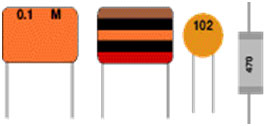
Image of various types of capacitors

Fig. 3: Image of various types of capacitors

The various types of capacitors are given below:
1.      Fixed capacitors
·         Film Capacitors like glass capacitor, mica capacitors, silver mica capacitor, ceramic capacitor, paper capacitor, metalized paper capacitor, polyester capacitor, polystyrene capacitor, metalized polyester capacitor, polycarbonate capacitor, polypropylene capacitors, Teflon capacitors, porcelain capacitor.
·          Electrolyte Capacitors like aluminum electrolyte, tantalum electrolyte, aluminum-tantalum electrolyte
2.      Variable capacitors

Fixed Capacitors
1.      FiXED capacitors
a.       Film capacitors
Film capacitors consist of a relatively large family of capacitors with the difference being in their dielectric properties. These include polyester (Mylar), polystyrene, polypropylene, polycarbonate, metalized paper, Teflon etc. Film type capacitors are available in capacitance ranges from 5pF to 100uF depending upon the actual type of capacitor and its voltage rating. Film capacitors come in various shapes and case styles such as:
·         Wrap and Fill (oval & round)  –  The capacitor is wrapped in a tight plastic tape and the ends are filled with epoxy in order  to seal them.
·         Epoxy Case (rectangular & round)  –  The capacitor is encased in a molded plastic shell which is filled with epoxy.
·         Metal hermetically sealed (rectangular & round)  –  The capacitor is encased in a metal tube or a can and sealed with epoxy.
 Note: All the above case styles are available in both Axial and Radial leads.
 
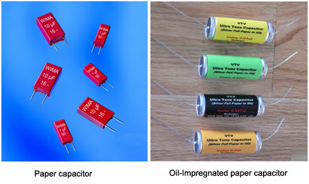
b.      Paper capacitor:
Paper capacitors are made of paper or oil-impregnated paper and aluminum foil layers rolled into a cylinder and sealed with wax. These capacitors were commonly used but are now replaced by the plastic or polymer type of capacitors. The paper capacitors are bulky, highly hygroscopic and soaks moisture which causes loss to the dielectric degrading its overall performance is the major drawback with this type of capacitors.  The other variants include oil-impregnated, paper-polyester and Kraft paper capacitor.  
Image of Paper Capacitors

Fig. 4: Image of Paper Capacitors

Image showing construction of Paper Capacitors

Fig. 5: Image showing construction of Paper Capacitors

Fixed Capacitors – 2

c.       Metalized paper capacitors:
The metalized paper capacitors are smaller in size than the conventional paper capacitors.  However, these capacitors are appropriate for only low current applications and are now replaced by metalized film capacitors.
Image of Metalized Paper Capacitors

Fig. 6:  Image of Metalized Paper Capacitors

d.      Mica capacitor:

The mica capacitor uses mica as the dielectric medium. Mica is inert in nature and hence the physical and chemical properties do not change as it ages. It provides good temperature stability and resistance to corona discharge i.e. electrical discharges due to ionization around conductor. However, the cost is very high and due to improper sealing the capacitor is highly prone to moisture which increases the power factor.
Image showing construction of Mica Capacitor
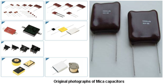
Fig. 7: Image showing construction of Mica Capacitor

Image of Mica Capacitors

Fig. 8: Image of Mica Capacitors

Fixed Capacitors – 3

e.       Silver Mica or metalized mica capacitor:  
These are a kind of mica capacitor which has an additional advantage of reduced moisture infiltration. These capacitors are expensive and are used often in HF and low VHF radio frequency circuits as low value accurate capacitors particularly in the oscillators and filters. The reasons that these capacitors are still in use regardless of high cost, large size and availability of other low cost capacitors are due to its remarkable features such as:
·         low tolerance of +/- 1%
·         positive temperature coefficient of 35 to 75 ppm/C
·         greater range from few pF to two or three pF
·         little voltage dependence,
·         high stability
·         Good Q factor.
 
However, these capacitors are not widely used these days.  
Image of Silver Mica Capacitor

Fig. 9:  Image of Silver Mica Capacitor

f.       Glass capacitor:
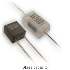
These capacitors are fabricated of glass dielectrics and are very expensive which are used for highly accurate, stable and reliable operation in harsh environmental conditions. These are resistant to nuclear radiations and available in range of 10pF to 1000pF.
Image of Glass Capacitor
Fig. 10: Image of Glass Capacitor

Fixed Capacitors – 4

g.      Ceramic capacitor:
The non – polarized type ceramic capacitors which are also known as ‘Disc capacitors’ are widely used these days. These are available in millions of varieties of cost and performance. The features of ceramic capacitor depend upon:
·         Type of ceramic dielectric used in the capacitor which varies in the temperature coefficient.  
·         Dielectric losses.
The exact formulas of the different ceramics used in ceramic capacitors vary from one manufacturer to another. The common compounds such as titanium dioxide, strontium titanate, and barium titanateare the three main types available although other types such as leaded disc ceramic capacitors for through hole mounting which are resin coated, multilayer surface mount chip ceramic capacitors and microwave bare leadless disc ceramic capacitors that are designed to sit in a slot in the PCB and are soldered in place.
These are made by placing silver coated ceramic plateson two sides and assembled together to form the capacitor. The surface mount version consists of the ceramic dielectric in which a number of interleaved precious metal electrodes are contained. This structure gives rise to a high capacitance per unit volume. The inner electrodes are connected to the two terminations, either by silver palladium (AgPd) alloy in the ratio 65 : 35, or silver dipped with a barrier layer of plated nickel and finally covered with a layer of plated tin (NiSn).  
The Electronics industries alliance (EIA) has broadly classified the ceramics used in these capacitors into 3 classes – class 1,class 2 and class 3.The lower is the class better are its overall characteristics but is on the cost of size. Each class defines the working temperature range, temperature drift, tolerance, etc. The typical values range from 10pF to 1uF. The capacitance values are labeled by three digit codes where the first two digits represent a number and the third digit is the multiplier digit.
For example: 103 means 10 * 103 pF which is 0.01uF
                           or
                      104 which is 10*104 pF which is 0.1uF
The tolerance is indicated by a letter like j=5%, K=10% and M=20%.
These capacitors are commonly used as a timing element in filter circuit and balancing oscillator circuits in radio frequency applications, coupling and decoupling networks.
The three ceramic classes decided by EIA are:
a.       Class1 – Class 1 ceramic capacitors are the most stable forms of ceramic capacitor with respect to temperature. The common compounds used as the dielectrics are magnesium titanate for a positive temperature coefficient (PTC), or calcium titanate for capacitors with a negative temperature coefficient (NTC). Using combinations of these and other compounds it is possible to obtain a dielectric constant of between 5 and 150. They have an almost linear characteristic and their properties are almost independent of frequency within normal bounds. Temperature coefficients between +40 and -5000 ppm/C can be obtained.

Class 1 capacitors offer the best performance with respect to dissipation factor. A typical figure may be 0.15%. It is also possible to obtain very high accuracy (~1%) class 1 capacitors rather than the more usual 5% or 10% tolerance versions. The highest accuracy class 1 capacitors are designated C0G or NP0.
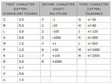
EIA has defined a set of codes in order to have a managed way of ceramic capacitor performance.  The codes of class 1 and class 2 capacitors are different.
The class 1 codes are as follows:  
Table listing Class 1 Codes for Ceramic Capacitors
Fig. 11: Table listing Class 1 Codes for Ceramic Capacitors
·         The first character is a letter which gives the significant figure of the change in capacitance over temperature in ppm/C.
·         The second character is numeric and gives the multiplier.
·         The third character is a letter and gives the maximum error in ppm/C.
One common example of class 1 capacitor is a C0G. This has 0 drift, with an error of 30PPM/C. 
Image of Class 1 Ceramic Capacitors
Fig. 12:  Image of Class 1 Ceramic Capacitors
b.      Class 2 – Class 2 capacitors are better in size, but have less accuracy and stability. As a result, they are normally used for decoupling, coupling and bypass applications where accuracy is not of prime importance. A typical class 2 capacitor may change capacitance by 15% or so over a -50C to +85C temperature range and it may have a dissipation factor of 2.5%. It will have average to poor accuracy (from 10% down to +20/-80%). However for many applications these figures would not present a problem.
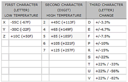
The class 2 codes are as follows:
Table listing Class 2 Codes for Ceramic Capacitors

 Fig. 13: Table listing Class 2 Codes for Ceramic Capacitors

                      .      The first character is a letter which gives the low-end operating temperature.
·         The second is numeric which provides the high-end operating temperature.
·         The third character is a letter which provides capacitance change over that temperature range.
The common examples of class 2 ceramic capacitors are:
·         The X7R capacitor which operates from -55C to +125C with a capacitance change of up to 15%.
·         The Z5U capacitor which operates from +10C to +85C with a capacitance change of up to +22% to -56%.              

Image of Class 2 Ceramic Capacitors

Fig. 14: Image of Class 2 Ceramic Capacitors

c.       Class 3 – Class 3 ceramic capacitors are small in size with less accuracy, stability and low dissipation factor. This type of capacitors cannot withstand high voltages.
Barium titanate that has a dielectric constant about 1250 is used as the dielectric. A typical class 3 capacitor will change its capacitance by -22% to +50% over a temperature range of +10C to +55C. It may also have a dissipation factor of around 3 to 5%. It will have a fairly poor accuracy (commonly, 20%, or -20/+80%). Therefore, class 3 ceramic capacitors are typically used as decoupling or in other power supply applications where accuracy is not of prime importance. However, they must not be used in applications where spikes are present as they cannot withstand high voltages.
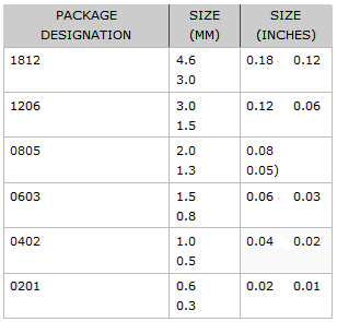
SMT ceramic capacitors are also available in standard packages which have following designations given in the below table.  
Table listing standard packages of SMT Ceramic Capacitors
Fig. 15: Table listing standard packages of SMT Ceramic Capacitors

Fixed Capacitors – 5

h. Plastic capacitors
                                i.            Polyester or PET capacitor:
Polyester or PET capacitors are plastic capacitors available as leaded packages that replace the paper capacitors. These capacitors are made of polyester films which small in size and available at low cost. These have Operating voltages up to 60,000 V DC, operating temperatures up to 125 °C and low moisture absorption. These are mostly used as low frequency signal capacitors and integrators. They are preferred where cost plays an important role because they have high tolerances of 5 – 10 %.
 
Image of Plastic Capacitors

Fig. 16: Image of Plastic Capacitors

                              ii.    Polystyrene capacitors:
These are large size capacitors available in tubular shape leaded packages. They have high stability, negative temperature coefficient (NTC), high accuracy and low moisture absorption. The operating temperature is limited to +85 C. These are mostly preferred for low frequency applications as the tubular structure induces inductances which degraded the performance at high frequencies.
Image of Polystyrene Capacitors

Fig. 17: Image of Polystyrene Capacitors
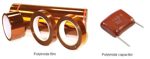
                            iii.            Kapton polyimide capacitor:
These capacitors are similar to polyester or PET capacitors that are made of Kapton polyimide film. They are expensive but offer high operating temperatures up to 250 C. These capacitors are not suitable for RF applications.
 
Image of Kapton Polyimide Capacitor

Fig. 18: Image of Kapton Polyimide Capacitor
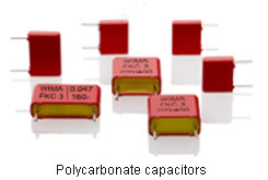
                            iv.            Polycarbonate capacitors:
These are high performance capacitors which are least affected as it ages. These are characterized by good insulation resistance and dissipation factor. The operating temperature ranges from -55 to +125 C. The dielectric constant is 3.2 %, and dielectric strength is 38 KV/mm. The dissipative factor is 0.0007 at 50Hz and 0.001 at 1MHz. The water absorption is 0.16%. These are mostly used for filters, coupling and timing applications. These can be directly replaced by Polyethylene napthalate (PEN), Polyphenylene sulphide (PPS), Polyimide (PI) and Polytetrafluoroethylene (PTFE).
 
Image of Polycarbonate Capacitors
Fig. 19: Image of Polycarbonate Capacitors
                              v.            Polypropylene capacitors:
These are used where higher tolerances than PET film capacitors are demanded. These are available in leaded packages and are used for low frequency operation. They have high operating voltages and are resistant to the breakdown.  However, they get damaged by transient over-voltages or voltage reversals.
 
Image of Polypropylene Capacitors
Fig. 20: Image of Polypropylene Capacitors
                            vi.            Polysulfone capacitor:
These capacitors are similar to polycarbonate capacitors but can withstand full voltage at comparatively higher temperatures. These capacitors are very expensive and are not readily available. The stability is limited as the moisture absorption is typically 0.2%
                          vii.            TEFLON or PTFE fluorocarbon capacitor:
These plastic capacitors are large in size and expensive. Due to low losses and higher stability these are used for some critical applications.  The operating temperature ranges up to 250 C. The dielectric used is Polytetrafluoroethylene.
 
Image of TEFLON or PTFE Fluorocarbon Capacitor

Fig. 21: Image of TEFLON or PTFE Fluorocarbon Capacitor

                        viii.            Polyamide capacitor:
   These plastic film capacitors are large in size and expensive. The operating temperature ranges up to 200 C.
                            ix.            Metalized polyester or Metalized plastic capacitor:
These capacitors have metalized plastic films which provide self heating advantage and also reduce the size of the capacitor over conventional plastic or polyester capacitor. However, they are limited by maximum current capacity. They are available in leaded package.
Image of Metalized Plastic Capacitor

Fig. 22: Image of Metalized Plastic Capacitor

Fixed Capacitors – 6

1. Electrolyte capacitors
                                i.            Aluminum electrolyte capacitor:
These polarized capacitors are made of oxide film on aluminum foils. These are cheaper and easily available. The range of values typically varies from 1uF to 47000uF and large tolerance of 20%. The voltage ratings range up to 500V. They have high capacitance to volume ratio and used for smoothing in power supply circuits or coupling capacitors in audio amplifiers. These are available in both leaded and surface mount packages. The capacitance value and voltage ratings are either printed in uF or coded by a letter followed by three digits. The three digits represent the capacitance value in pF where first two digits represent the number and the third one is the multiplier digit. The letter codes are as follows:
Table listing letter code for Aluminum Electrolyte Capacitors
Fig. 23: Table listing letter code for Aluminum Electrolyte Capacitors
Image of Aluminum Electrolyte Capacitors

Fig. 24: Image of  Aluminum Electrolyte Capacitors

                              ii.            Tantalum electrolyte capacitor:
These capacitors utilize tantalum oxide which enables the fabrication of small size electrolytes. These are costlier than aluminum electrolytes and have lower maximum voltage up to 50V and are preferred where size matters. Their typical values range from 47uF to 470uF. These may be using tantalum oxide layered foils or porous anode with sulphuric acid as electrolyte in between tantalum foils in a wet tantalum electrolyte or solid tantalum electrolytes. Their SMT formats are available in standard packages where package designations have been defined by the EIA.
 
Image showing construction of Tantalum Electrolyte Capacitor

Fig. 25: Image showing construction of Tantalum Electrolyte Capacitor
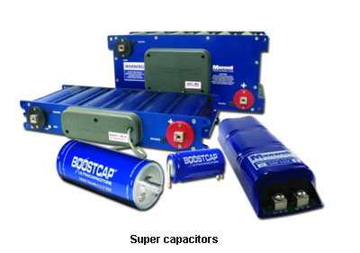
Image of Tantalum Electrolyte Capacitors
Fig. 26: Image of Tantalum Electrolyte Capacitors
                            iii.            Super capacitor:
Super capacitors also called as electrolyte double layer capacitorare made of a thin electrolyte separator flanked with activated carbon ions. These have capacitance values as high as of order of mille farads. These are used as temporary power source as a replacement of batteries.   
Image of Super Capacitors

Fig. 27: Image of Super Capacitors

Variable Capacitors

2.      Variable capacitors
The variable type of capacitors can vary the capacitance by changing the distance between the plates or the effective area of the capacitor.
a.       Air-gap capacitors:
These capacitors use air as the dielectric medium. The distance between the plates can be varied to change the capacitance. The capacitance values offered are high and can be used with high voltages. These are used for high frequency operations in communication systems.
b.      Vacuum capacitors:
These capacitors have glass or ceramic encapsulation and vacuum as the dielectric. Their complex construction makes it very expensive. Theoretically, it has less losses and are used in RF applications.
 
Image showing construction of Trimmer
Fig. 28:  Image showing construction of Trimmer
Image showing working principle of variable capacitor
Fig. 29:  Image showing working principle of variable capacitor
Image of Variable Capacitors

Fig. 30: Image of Variable Capacitors

Capacitor Color Code

 Capacitor Color Code:  
Image showing color coding for Capacitors

Fig. 31: Image showing color coding for Capacitors

A color code was used on polyester capacitors for many years. It is now obsolete, but of course there are many still around. The colors should be read like the resistor code.  
·         The top three color bands give the value in pF.
·         The 4th band is for tolerance.
·         The 5th band is for the voltage rating.
For example:
          i.            brown, black, orange   means 10000pF = 10nF = 0.01µF.
Note: There are no gaps between the colour bands, so 2 identical bands actually appear as a wide band.
        ii.            wide red, yellow   means 220nF = 0.22µF.

You may also like:


  • What are the different types of integrated circuits?

  • What is an SoC?

  • What is a low power design?

  • What is the 1-Wire protocol?

  • Testing MOSFET – (Part 16/17)

Filed Under: Tutorials
Tagged With: capacitor, charging, discharging, parallel plate
 

Next Article

← Previous Article
Next Article →

Questions related to this article?
👉Ask and discuss on EDAboard.com and Electro-Tech-Online.com forums.


Tell Us What You Think!! Cancel reply

You must be logged in to post a comment.

EE TECH TOOLBOX

“ee
Tech Toolbox: Internet of Things
Explore practical strategies for minimizing attack surfaces, managing memory efficiently, and securing firmware. Download now to ensure your IoT implementations remain secure, efficient, and future-ready.

EE Learning Center

EE Learning Center
“engineers
EXPAND YOUR KNOWLEDGE AND STAY CONNECTED
Get the latest info on technologies, tools and strategies for EE professionals.

HAVE A QUESTION?

Have a technical question about an article or other engineering questions? Check out our engineering forums EDABoard.com and Electro-Tech-Online.com where you can get those questions asked and answered by your peers!


RSS EDABOARD.com Discussions

  • surge+EMI filter
  • Input impedance matching network
  • How to preserve hierarchical instance names like \adder_1/U1 in flattened gate-level netlist in Design Compiler?
  • Can anyone provide a guide or tutorial for Candece simulation?
  • Voltage mode pushpull is a nonsense SMPS?

RSS Electro-Tech-Online.com Discussions

  • Can I make two inputs from one??
  • Photo interrupter Connections
  • Is AI making embedded software developers more productive?
  • Why can't I breadboard this oscillator?
  • Cataract Lens Options?

Featured – RPi Python Programming (27 Part)

  • RPi Python Programming 21: The SIM900A AT commands
  • RPi Python Programming 22: Calls & SMS using a SIM900A GSM-GPRS modem
  • RPi Python Programming 23: Interfacing a NEO-6MV2 GPS module with Raspberry Pi
  • RPi Python Programming 24: I2C explained
  • RPi Python Programming 25 – Synchronous serial communication in Raspberry Pi using I2C protocol
  • RPi Python Programming 26 – Interfacing ADXL345 accelerometer sensor with Raspberry Pi

Recent Articles

  • GigaDevice launches GD32C231 MCU series with 48MHz Cortex-M23 core and 64KB Flash
  • Advanced Energy releases 425 W CF-rated medical power supply in 3.5 x 6 x 1.5-inch format”
  • LEM combines shunt and Hall effect sensing in 2000 A current measurement unit
  • What is AWS IoT Core and when should you use it?
  • AC-DC power supply extends voltage range to 800 V DC

EE ENGINEERING TRAINING DAYS

engineering

Submit a Guest Post

submit a guest post
Engineers Garage
  • Analog IC TIps
  • Connector Tips
  • Battery Power Tips
  • DesignFast
  • EDABoard Forums
  • EE World Online
  • Electro-Tech-Online Forums
  • EV Engineering
  • Microcontroller Tips
  • Power Electronic Tips
  • Sensor Tips
  • Test and Measurement Tips
  • 5G Technology World
  • Subscribe to our newsletter
  • About Us
  • Contact Us
  • Advertise

Copyright © 2025 WTWH Media LLC. All Rights Reserved. The material on this site may not be reproduced, distributed, transmitted, cached or otherwise used, except with the prior written permission of WTWH Media
Privacy Policy

Search Engineers Garage

  • Electronic Projects & Tutorials
    • Electronic Projects
      • Arduino Projects
      • AVR
      • Raspberry pi
      • ESP8266
      • BeagleBone
      • 8051 Microcontroller
      • ARM
      • PIC Microcontroller
      • STM32
    • Tutorials
      • Audio Electronics
      • Battery Management
      • Brainwave
      • Electric Vehicles
      • EMI/EMC/RFI
      • Hardware Filters
      • IoT tutorials
      • Power Tutorials
      • Python
      • Sensors
      • USB
      • VHDL
    • Circuit Design
    • Project Videos
    • Components
  • Articles
    • Tech Articles
    • Insight
    • Invention Stories
    • How to
    • What Is
  • News
    • Electronic Product News
    • Business News
    • Company/Start-up News
    • DIY Reviews
    • Guest Post
  • Forums
    • EDABoard.com
    • Electro-Tech-Online
    • EG Forum Archive
  • DigiKey Store
    • Cables, Wires
    • Connectors, Interconnect
    • Discrete
    • Electromechanical
    • Embedded Computers
    • Enclosures, Hardware, Office
    • Integrated Circuits (ICs)
    • Isolators
    • LED/Optoelectronics
    • Passive
    • Power, Circuit Protection
    • Programmers
    • RF, Wireless
    • Semiconductors
    • Sensors, Transducers
    • Test Products
    • Tools
  • Learn
    • eBooks/Tech Tips
    • Design Guides
    • Learning Center
    • Tech Toolboxes
    • Webinars & Digital Events
  • Resources
    • Digital Issues
    • EE Training Days
    • LEAP Awards
    • Podcasts
    • Webinars / Digital Events
    • White Papers
    • Engineering Diversity & Inclusion
    • DesignFast
  • Guest Post Guidelines
  • Advertise
  • Subscribe