Many of you might have seen the automatic doors with a card lock system. The card replaces the key. The door unlocks/locks with particular card only. User has to insert that particular card to unlock and open the door and also he has to use same card to lock/close the door. If anyone attempts to enter any other card the door does not unlock/open and gives audio-visual warning or an alarm. Such kinds of systems are installed where unauthorized access or trespassing is prohibited. Such system prevents entry of any unauthorized person to any secured premises. Such systems are very sophisticated systems with very high level of security with encoding – decoding and encryption-decryption.
The given project is a just a demonstration of such system. It shows how punch hole cards can be used lock/unlock the automatic door. The system uses opto-interrupt sensors and micro-controller AT89C51 to detect correct card. The LCD is used to display different messages. The stepper motor is used as an illustration of opening/closing door.
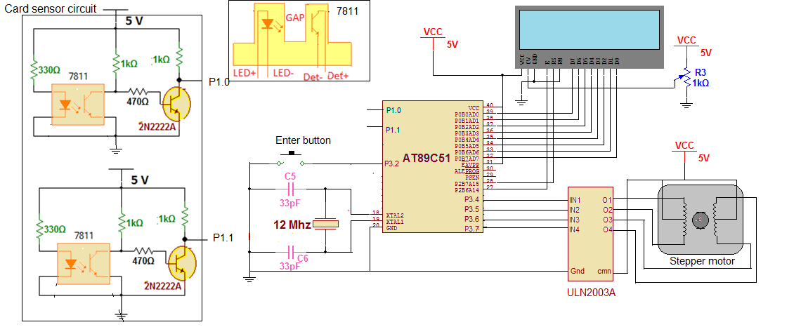
Card sensor circuit
The main circuit consist of one sub circuit – card sensor circuit. The card sensor circuit is built using two opto-interrupt sensor MOC7811 chips that is actually combination of IR LED and photo transistor. There is very small gap (as shown in figure) in between LED and photo transistor. There are two identical circuits. The LED is given direct supply through current limiting resistor of 330E. The collector output of photo transistor drives another npn transistor 2n2222A. The transistor is connected in switch mode. The final two outputs of circuit are taken from collectors of npn transistors. These two outputs are given to micro controller.
Main circuit
Main circuit is built using micro controller AT89C51, LCD and motor driver chip UNL2003A.
· The outputs of card sensor circuits are given as input to port P1 pins P1.0 and P1.1
· One push button is connected to external interrupt 0 pin P3.2 to generate interrupt when button is pressed
· Port P0 is an output port and it drives data pins of LCD D0 – D7.Further two pins of port P2 P2.7 and P2.6 are connected to control pins of LCD Rs and E. The third control pin RW is permanently connected to ground to make LCD always write enable
· A 1 K pot is connected to brightness control pin Vee of LCD to vary its brightness
· Port P3 pins P3.4 – P3.7 drives stepper motor through motor driver chip ULN2003A. The motor opens or closes the door
· A 12 MHz crystal is connected between XTAL pins along with two biasing capacitors of 33 pf. It provides clock signal to micro controller
· The circuit is given power supply through 5 V
Circuit operation:
First let us see how card sensor circuit detects different types of cards. The cards are actually punch cards with holes at specific places as shown in figure. There are many different cards as per the different positions and combinations of punch holes. The given figure illustrates how four different cards generate four different possible combinations of output. As shown in figure when card 1 is inserted it has two punch holes exactly under the sensor gap position. So both sensor conduct and give output 1. For card 2 there is a hole at sensor 1 position but no hole for sensor 2. So sensor 1 output is 1 but sensor 2 output is 0. Means if there is a hole in the inserted card between sensor gap position, its output will be high (1) or low (0) otherwise. This is how the sensor circuit distinguish different cards and generate different output combinations as 00, 01, 10 and 11.

Fig. 1: Overview of Automatic Card Lock System
Now let us see the operation of entire circuit.
· When the system is powered ON, the door is locked and the message is displayed on LCD as “To unlock door Enter card”.
· User has to insert a card and press enter button
· The micro controller will detect the card. It will match the punch card pattern with internal stored pattern
· If it matches, the motor rotates clockwise to unlock the door and the message is displayed on LCD as “door unlocked access granted”.
· Once door is unlocked, the message is displayed on screen as “to lock door enter card”. So user has to again insert card and press enter to lock it.
If entered card pattern does not match the motor stand stills and message displayed as “wrong card access denied”. Also if wrong card is inserted for 3 times, the system enters into infinite loop (means it hangs) and LCD displays “3 attempts over system hangs”
Project Source Code
###
#include<reg51.h>
#include <string.h>
sbit rs = P2^7; // rs pin of LCD
sbit en = P2^6; // en pin of LCD
sbit lock_led = P2^2;
sbit unlock_led = P2^1;
sbit hang_led = P2^0;
unsigned int count=0;
unsigned char p1_status;
void delay(int z)
{
unsigned int x,y;
for(x=0;x<z;x++)
for(y=0;y<10000;y++);
}
void lcddly()
{
int a;
for(a=0;a<1500;a++);
}
void writecmd(unsigned char a)
{
lcddly();
rs = 0;
P0 = a;
en = 1;
en = 0;
}
void writedata(unsigned char b)
{
lcddly();
rs = 1;
P0 = b;
en = 1;
en = 0;
}
void writestr(unsigned char *s)
{
unsigned char l,i;
l = strlen(s);
for(i=0;i<l;i++)
{
writedata(*s);
s++;
}
}
void motor_delay()
{
int p;
for(p=0;p<2000;p++);
}
void open_door()
{
unsigned int i;
for(i=0;i<128;i++)
{
P3 = 0x8F;
motor_delay();
P3 = 0x4F;
motor_delay();
P3 = 0x2F;
motor_delay();
P3 = 0x1F;
motor_delay();
}
}
void close_door()
{
unsigned int i;
for(i=0;i<128;i++)
{
P3 = 0x1F;
motor_delay();
P3 = 0x2F;
motor_delay();
P3 = 0x4F;
motor_delay();
P3 = 0x8F;
motor_delay();
}
}
void ext_int_0() interrupt 0
{
p1_status=P1;
delay(5);
}
void main()
{
int attempt_count=0,door_lock_flag=1;
P0=0x00;
P2=0x00;
P3 = 0x0F;
IE = 0x81;
lock_led=0;
unlock_led=1;
writecmd(0x3C);
writecmd(0x0E);
next:writecmd(0x01);
if(door_lock_flag==1) writestr("to unlock door");
else writestr("to lock door");
writecmd(0xC0);
writestr("Enter Card");
P1=0xFF;
p1_status=0xFF;
while(p1_status==0xFF);
if(p1_status==0xFE)
{
count++;
attempt_count=0;
if((count%2)==1)
{
writecmd(0x01);
writestr("door unlocked");
writecmd(0xC0);
writestr("Access Granted");
lock_led=1;
unlock_led=0;
open_door();
door_lock_flag=0;
}
else
{
writecmd(0x01);
writestr("door locked") ;
lock_led=0;
unlock_led=1;
close_door();
door_lock_flag=1;
}
}
else
{
writecmd(0x01);
writestr("wrong card");
writecmd(0xC0);
writestr("Access Denied");
attempt_count++;
}
delay(40);
if(attempt_count==3)
{
writecmd(0x01);
writestr("3 attempts over ");
writecmd(0xC0);
writestr("system hang");
hang_led=0;
while(1);
}
else goto next;
}
###
Circuit Diagrams
Project Video
Filed Under: Electronic Projects
Filed Under: Electronic Projects

Questions related to this article?
👉Ask and discuss on Electro-Tech-Online.com and EDAboard.com forums.
Tell Us What You Think!!
You must be logged in to post a comment.