Conventionally, wireless controlled robots uses circuits, which have a drawback of limited working range, limited frequency range and limited control. Use of mobile phones for robotic control can overcome these limitations. It provides the advantages of robust control, working range as large as the coverage area of the service provider, no interference with other controllers and up to twelve controls.
Although, the appearance and capabilities of robot vary vastly, all robots share the feature of a mechanical, movables structure under some form of control. The control of robot involves three distant phases: perception, processing, action. Generally, the preceptors are sensors mounted on the robot, processing is done by the on board microcontroller and the task is performed using motors or with some other actuators.It is assumed that the reader has gone through the project How to get started with AVR and done all the things discussed in it.
In the project the pick and place robot is controlled by a mobile phone that makes a call to the mobile phone attached to the robot. In the course of a call, if any button is pressed a tone corresponding to the button pressed is heard at the other end called ‘Dual Tone Multiple frequency’ (DTMF) tone. The robot receives these tones with help of phone stacked in the robot. The received tone is processed by the microcontroller with the help of DTMF decoder IC MT8870. These IC sends a signals to the motor driver IC l293d which drives the motor in directions forward, reverse, left, right, pick, release, up, down, rotate left, rotate right.

Fig. 1: Prototype of Mobile operated Pick and Place Robot
The important components of this robot are a DTMF decoder, microcontroller and motor driver.A CM8870 series DTMF decoder is used here. All types of the CM8870 series use digital counting techniques to detect and decode all the 16 DTMF tone pairs into a 4-bit code output. The built-in dial tone rejection circuit eliminates the need of pre-filtering.
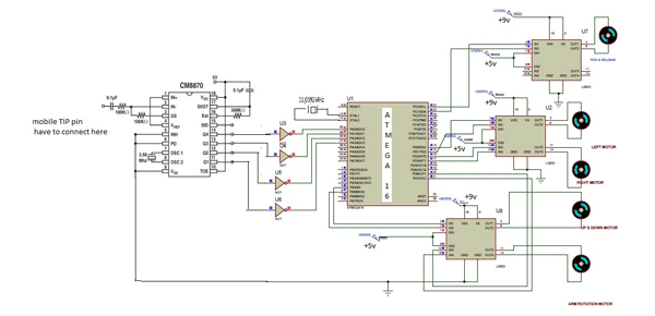
In circuit diagram atmega1616 microcontroller pin 9 is connected to push button for reset. Pins 10,30 is connected to vcc +5v and pins no: 11,31 is connected to GND. From DTMF decoder IC m8870 the output pins is connected to NOT gate IC 74LS04. From the NOT gates output is directly connected to atmega16 pins 40,39,38,37.
Input signals are given at PORTA pins 40,39,38,37 differential input configuration is recognized to be effective, the correct 4-bit decode signal of the DTMF tone is transferred to Microcontroller. The pin11 to pin14 of DTMF decoder are connected to the pins of microcontroller (pins 40,39,38,37).

Fig. 2: Image showing Mobile operated Pick and Place Robot in action
The atmega16 is a 8-bit microcontroller, has 64 kB Flash microcontroller with 1kB RAM. it provides the following features: 64 kB of on-chip Flash program memory with ISP (In-System Programming).
Output from the micro controller is given to the motors through motor driver IC L293D. in this project there are 5 motors to control pick and place robot. Two motors are used to move robot front, backward, left, right. These two motors are connected to microcontroller pin 14 to pin 17. If binary codes 0010,0100,0110,1000 received from DTMF decoder IC and inverted these codes using NOT GATES and these codes applied to micro controller pins 37 to 40.
The microcontroller drives the motors in clock wise direction if the code received from DTMF is ‘0010’. Two motors Then robot will moves in forward direction.
If the code received from DTMF is ‘1000’ the robot will moves in the back ward directions. If the code received from DTMF is ‘0100’ motor 1 will be in anti clock wise direction and motor 2 will be in clock wise direction then robot will turns left.
If the code received from DTMF is ‘0110’ motor 1 will be in clock wise direction and motor 2 will be in anti clock wise direction then robot will turns right.
Remaining 3 motors are used for robot arm controlling. one motor is used for pick & release and 2nd motor is used for movement of robot arm up & down directions and 3rd motor is used for robot arm to rotate clock wise & anticlockwise directions.
For picking object the motor drives is connected at the pins 22,23 of the microcontroller. Robot arm for upward and downward directions the motors connected at the pins 5,6. The arm rotation clockwise and anticlockwise direction the motor driver is connected at pins 20,21.

Fig. 3: Image showing robotic arm mounted on Pick and Place Robot
Details
The table given below shows the codes which will operate the robot.
|
key |
operation |
|
1 |
Picks the object |
|
2 |
Robot moves in forward direction |
|
3 |
Releases the object |
|
4 |
Robot turns left direction |
|
5 |
Robot arm moves up ward direction |
|
6 |
Robot turns right direction |
|
7 |
Robot arm rotates in clockwise direction |
|
8 |
robot moves backward direction |
|
9 |
Robot arm rotates in anticlockwise direction |
|
0 |
Robot arm moves down ward direction |
|
# |
To stop robot all motors. |

Fig. 4: Block Diagram of Mobile Operated Pickk and Place Robo
The main part of the project is mechanical arrangement of robot arm by using 3 motors. We can develop the robot arm with help of 4 or 5 motors according to our design. In this project we used only 3 motors for controlling robot arm. The below diagram shows the robot arm arrangement.
SOFTWARES USED:
AVR STUDIO4 software for generating hex file.
proteus software is used for simulating the circuit.
Dual Tone Multiple Frequency – DTMF
DTMF stands for dual tone multiple frequency. DTMF is a term which used in telephone industry. When any key on telephone or mobile phone is pressed one tone is generated and it is audible which is nothing but a DTMF tone. To decode DTMF tone from mobile phone we need MT8870 DTMF decoder IC, 3.5mm male and female connector.

Fig. 5: Representational Image for DTMF
What is DTMF Code?
When any of the key like “1”, “2”, “*”, “#” etc is pressed particular code is transmitted. This code is consist of two frequency among which one is higher frequency and second one is lower frequency. Following table shows the combination of frequency for respected keys.

Fig. 6: Table showing key mapping respective to DTMF Frequencies
According to above table “8” is combination of lower frequency of 852 Hz and higher frequency of 1336 Hz and “#” is of lower frequency of 941 Hz and higher frequency of 1447 Hz. So this is all about DTMF code, now let see about how DTMF code are generated, transmitted and Decoded in mobile phone system. Here i am only talk about GSM system.
Decoding DTMF code:
When any DTMF code has been received at mobile phone it can be audible through speaker. So to decode this DTMF code speaker output it self can be used. Output of speaker is connected to IC MT8870 which is DTMF decoder IC. It used widely to decode DTMF code. It gives 4-bit digital output q1, q2, q3, and q4 according to the received key. Following table shows the equivalent digital output for each key.

Fig. 7: Table listing digital outputs corresponding to DTMF Keys

FIg. 8: PCB Layout of AVR ATMega16 based controller circuitry for Mobile operated Pick and Place Robot
Project Source Code
###


#define F_CPU 1000000UL
#include <avr/io.h>
#include <util/delay.h>
void main(void)
{
unsigned int k,h;
DDRA=0x00;
DDRB=0xFF;
DDRD=0XFF;
DDRC=0xFF;
while (1)
{
k =~PINA;
h=k & 0x0F;
switch (h)
{
case 0x01:
{
PORTC=0x01;// picks the object
PORTB=0x00;
PORTD=0x00;
break;
}
case 0x02:
{
PORTB=0x00; // moves forward direction
PORTC=0x00;
PORTD=0x09;
break;
}
case 0x03:
{
PORTC=0x02; // releases the object
PORTB=0x00;
PORTD=0x00;
break;
}
case 0x04:
{
PORTC=0x00;
PORTB=0x00;
PORTD=0x0A; // left turn
break;
}
case 0x05:
{
PORTC=0x00; // arm rotation in left direction
PORTB=0x00;
PORTD=0x80;
break;
}
case 0x06:
{
PORTC=0x00;
PORTB=0x00;
PORTD=0x05; // right turn
break;
}
case 0x07:
{
PORTC=0x00;  // arm moves up direction
PORTD=0x00;
PORTB=0x20;
break;
}
case 0x08:
{
PORTC=0x00;  // robot moves backward direction
PORTB=0x00;
PORTD=0x06;
break;
}
case 0x09:
{
PORTD=0x00;  // arm moves down direction
PORTC=0x00;
PORTB=0x10;
break;
}
case 0x0A:
{
PORTC=0x00;  // arm rotation in right direction
PORTB=0x00;
PORTD=0x40;
break;
}
case 0x0B:
{
PORTB=0x00;  // to stop the pick & place robot for all operations
PORTD=0x00;
PORTC=0X00;
break;
}
default:
{
PORTD=0x00;
PORTC=0x00;
PORTB=0x00;
}
}
}
}


###
Circuit Diagrams
Project Video
Filed Under: Electronic Projects
Filed Under: Electronic Projects

Questions related to this article?
👉Ask and discuss on Electro-Tech-Online.com and EDAboard.com forums.
Tell Us What You Think!!
You must be logged in to post a comment.