Robots are mechanical devices equipped with software-based intelligence that can perform specific physical tasks. There are many kinds of robots and robotic applications. The robots are designed to suit their application and their mechanical design, body, electronics, and software are designed accordingly. The robotic vehicles or robotic cars are one of the many types of robotic designs. The robotic cars are designed to move around plain surfaces where they can perform certain tasks either through remote controlling or autonomously. They are equipped with sensors, control circuitry and actuators for their operation.
The motion of such a robot itself requires the use of motors. There are many kinds of motors which can be used in robotic applications. Each type of motor is used for different purpose. The motors aid in the motion of the robot as well as serve as actuators in the mechanical design of the robot. A robotic application may involve the following types of motion –
1) Vertical motion – moving a part of robot up and down usually by means of shoulder swivel
2) Radial motion – Moving a part of robot in and out
3) Rotational motion – Clockwise or anticlockwise rotation about vertical or horizontal axis or about a plane in three-dimensional frame
4) Pitch motion – Up and down movement with simultaneous rotational motion
5) Roll motion – Rotation of a part of robot with reference to the rest of the robotic body in a parallel axis
6) Yaw motion – Rightward or Leftward swiveling motion of a part of robot
7) Locomotion – movement of robot over a surface or in a medium
All these types of motion are realized with the help of various motors or pumps assembled along with transmission systems and end-effectors. In this tutorial, the use of motors to provide primary motion to a robot itself or its part will be discussed. The tutorial will look into different types of motors, their applications, selection of a motor and design of a robotic car.
Types of Motors
There are many types of motors available in the industry. For robotic applications, there are certain types of motors that are normally used. The motors normally used in robotic applications can be classified as follow –
• AC motor
• Brushed DC motor
• Brushless DC motor
• Geared DC motor
• Servo motor
• Stepper motor
AC Motor –
The AC motors are driven by AC current. They are normally used in heavy applications where high torque (high load carrying or load bearing capacity) is required. That is why these motors are used in robotic assembly lines deployed in manufacturing units. The movable robots are usually powered by DC sources (Batteries or Battery Series), that is why AC motors are rarely used in such robots.
Brushed DC Motor –
The brushed DC motors use the brushes to conduct current between the source and the armature. There are several variations of the brushed DC motor, but in robotics, permanent magnet DC motors are used. These motors are known for high torque to inertia ratio. The brush DC motors have the ability to provide the torque three to four times greater than their rated torque. The Brush DC motors consist of six different components: axle, commutator, armature, stator, magnets, and brushes.
The Brush DC Motors have two terminals. When the voltage is applied across the two terminals, a proportional speed is outputted to the shaft of the Brush DC Motor. A Brush DC Motor consists of two pieces: the stator which includes the housing, permanent magnets, and brushes, and the rotor, which consists of the output shaft, windings, and commutator. Its stator remains stationary, while the rotor rotates with respect to the stator. The stator generates a stationary magnetic field that surrounds the rotor.
The rotor, also called the armature, is made up of one or more windings. When these windings are energized they produce a magnetic field. The magnetic poles of this rotor field are attracted to the opposite poles generated by the stator, causing the rotor to turn. As the motor turns, the windings are constantly being energized in a different sequence so that the magnetic poles generated by the rotor do not overrun the poles generated in the stator. This switching of the field in the rotor windings is called commutation.
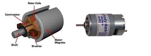
Fig. 1: Image Explaining Construction of a Brush DC Motor
Geared DC Motors –
The geared DC motors are an advanced variation of the brush DC motors. They have a gear assembly attached to the motor. The speed of the motor is measured in Rotation Per Minute (RPM). The speed of the motor is reduced with an increase in torque with the help of gear assembly. By using a correct combination of the gears to motor the speed of the DC motor can be reduced with an increase in torque. This provides stability in the rotation of the motor and the motor can be stopped or changed speed in a controlled manner.
The DC motors work in a specified range of the voltage and higher is the input voltage, higher is the RPM. For Example, if the motor works in the range of 6-12V, it has the least RPM at the input voltage of 6V and the maximum RPM at the input voltage of 12V.
The working of the gears in such motor is most interesting. It is based on the principle of conservation of angular momentum. The gears having smaller radius cover more RPM than the one with a larger radius. However, the larger gear will give more torque to the smaller gear and vice versa. The comparison of angular velocity between input gear (the one that transfers energy) to output gear gives the gear ratio. When multiple gears are connected together, conservation of energy is followed. The direction in which the other gear rotates is always opposite of the gear adjacent to it. In any DC motor, RPM and torque are inversely proportional. Hence the gear having more torque will provide a lesser RPM and converse. For controlling a geared DC motor, pulse width modulation technique is applied.
The torque and RPM of a geared DC motor depend upon the gear ratio. For example, suppose a DC motor may run at the speed of 12000 RPM and provide 12 kg-cm torque. By adding a 255:1 gear down, the speed of the motor can be reduced and torque can be increased. So, by adding 255:1 gear down, the resultant RPM is reduced to 53.3 (12000 rpm / 225) and torque is increased to 22.5 kg-cm (0.1 x 225). The motor now is able to move significantly more weight at a reasonable speed.
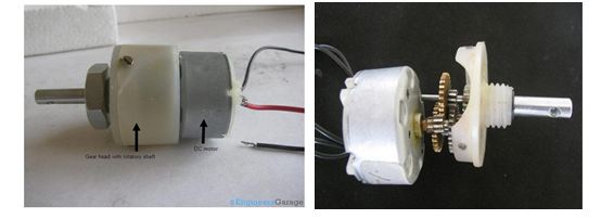
Fig. 2: Close View of Brush DC Motor (Right) and Geared DC Motor (Left)
For controlling geared DC motors, L293D motor driver IC is normally used in hobby robots. The IC is interfaced with a microcontroller to control the direction and speed of the DC motor. The Motor controller acts as the intermediate device between the motor, controller and the batteries. Although the microcontroller decides the speed and direction of the motor, it cannot directly control the motor because of limited power output. Even the motor controller can provide the power to the motor but cannot instruct the motor in which direction it should turn. Therefore, the motor controller and the microcontroller have to work together in order to control the motor.
In order to control the DC motor, H-Bridge circuit is needed that allows the voltage to be applied across a load in either direction. The L293D is a dual H-bridge motor driver integrated circuit (IC). The Motor drivers act as current amplifiers since they take a low-current control signal and provide a higher-current signal. This higher current signal is used to drive the motors. It has 16 pins with following pin configuration:

Fig. 3: Table Showing Configuration of PINs in a DC Motor
The IC can drive up to 1 amp of current and operate between 4.5V and 36V. For more information on motor driver IC, refer to L293D IC reference.
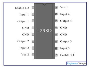
Fig. 4: PIN Diagram of L293D IC Used In DC Motor of Robots
Small motors are engineered for applications where compactness is valued over torque. While there are small high-torque motors, these tend to be expensive because they use rare earth magnets, high-efficiency bearings and other features that add to their cost. Large motors may produce more torque but also require higher currents.
High current motors require larger capacity batteries and bigger control circuits that won’t overheat and burn out under the load. Therefore, for matching the size of the motor with the rest of the robot, it is wise not to overload a small robot with a large motor. While deciding the size of the motor, available torque after gear reduction should be considered. Gear reduction always increases torque. The increase in torque is proportional to the amount of gear reduction. Like if the reduction is 3:1, the torque is increased by about three times.
Servo Motor –
Servo motors are normally used where precise rotational motion is required. They are frequently used in robotic arms and angle control applications. Learn more about servo motors and their control from Servo Motor tutorial.
Stepper Motor –
A stepper motor divides the rotation into multiple steps. Like the servo motor rotates by a specific angle, a stepper motor rotates by a specific number of angular steps. Learn more about stepper motor from the Tutorial on Stepper Motor.
Brushless DC Motor –
Brushless DC motors are similar to Brushed DC motors in construction but they are driven by closed loop controllers and require inverters or SMPS for power supply. These motors have permanent magnets which rotate a fixed armature. In contrast to Brush DC motors, they have closed loop electronic controller in place of commutator assembly. These motors are normally used in industrial robotics where precise control over motion and positioning is required. However, these motors are quite expensive and have complex construction and electronics involved.
Selecting a motor for a Robot
To select a proper electric motor one has to consider many different parameters like the load that a specific motor can handle, the torque required to move the robot without being overloaded, the rotations per minute of the motor when it is loaded, etc.
As there are many types of motors, depending on the application one of the motor type should be selected. For example, to run the robotic arm, servos are normally used. The wheeled robots have a simple design and navigate over the ground using motorized wheels. The wheels are also easier to design and build compared with tracks or legs. Using wheels has disadvantages like the navigation over obstacles or areas with low friction is not easy with wheels.
Most common electric motors used in such robots are the DC motors. The DC motors provide a high torque and have high efficiency. By applying torque in response to load, the DC motors can be characterized by the speed and torque curve. Commonly preferred voltage ratings of DC motors used in hobby robots are 3, 6, 12 and 24 Volts. If a motor is applied with a voltage lower than the voltage given in the data sheet, the torque will not overcome the internal friction – mostly from the brushes. Also, if a higher voltage than that supported is applied to the motor, it may get heat up and can get damaged.
Wheel combinations for a Robotic car
According to the laws of physics, a high weight requires strong forces to accelerate. This means that a heavier robot requires stronger motors in order to accelerate the body. To the forces acting due to the weight of the robot are added the frictional forces of the wheels and the internal friction inside the motor. On taking into account that a robot should climb stairs or run on inclined surfaces, other forces should also be considered, such as the gravitational force.
A motor can maintain a constant speed only if the torque is greater than the combined forces in opposite to the robot’s movement. In case that the motor torque is smaller than the opposition torque, the motor will stop and may be damaged since the electrical energy cannot be converted into torque.
For movement, the robots use differential steering that separately drive the wheels. The robot can change the direction of rotating each wheel at different speeds, and by adding additional wheels that are not driven by actuators, the robot can keep its balance.
Two wheels plus a caster or four wheels are the most common combinations for wheeled robots. Both combinations of wheels can turn in place and are known as a differential drive for two wheel version, while the four wheels have to be driven independently to turn in place.
• Two Wheels Plus Caster Wheel Robot –
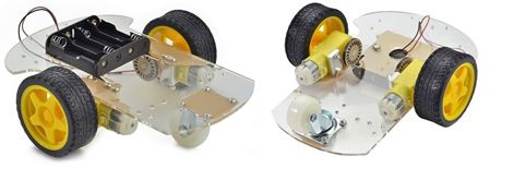
Fig. 5: Image Showing Two Wheel and a Castor Robot
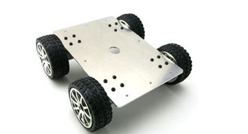
• Four Wheel Robot –
Fig. 5: A Typical Four Wheel Robot
The two wheels and a caster method have its advantages including the possibility to measure the movement by adding encoders. For the four-wheel method, adding an encoder could generate inaccurate measurements compared with real movements of the robot, but at the same time, this system is the best for closed-loop control and provide high grip for tires.
Calculation involved in the selection of a Motor
There are lots of mathematical calculations involved in finding the motor for the robot based on many parameters like torque, speed, rpm etc. Check out the calculations involved in the selection of a motor from Botskool website. Using an online calculator is perhaps the simplest and most precise method to find which electrical motor fit for a project. These calculators require input data based on properties and capabilities that one wishes for a robot, while the results are the specifications of the motor. Some website links for calculation of required motor specifications are given below –
Filed Under: Applications, Robotics, Tech Articles


Questions related to this article?
👉Ask and discuss on Electro-Tech-Online.com and EDAboard.com forums.
Tell Us What You Think!!
You must be logged in to post a comment.