Many of us have habit of not to save the data or work while working on system and lost our valuable work and time while working, as UPS shuts off automatically because of low batter. There are some software available in market which will give you indication that your system is going to shut down but they are very costly and some free ware are also available but they may contain threat of viruses that may damage your PC.
So we have described a simple circuit which will automatically hybernate your PC before UPS battery goes off. And important feature of this circuit is it will not require any software to be installed on your PC.
This circuit will also give you indication with the help of LED before preset time that you system is going to shut down. And this will give a enough time to save your work.
[[wysiwyg_imageupload:11690:]]
Fig. 1: Prototype for Automatically Hinernate PC Circuit on Breadboard
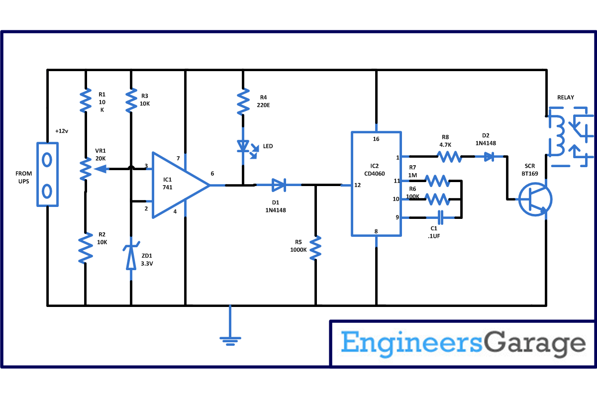
Initially when UPS is charge voltage at non inverting pin that is pin 3 is usually high in compare to inverting pin that is pin 2. This will make the output pin 6 of IC1 also high which in turn connected to pin 12 of IC2. Pin 12 of IC2 is known as reset pin and if this pin is made high or connected to power supply than IC2 will not work means this IC will not oscillate and counter will not start, therefore your system will work normally.
Now when your UPS battery becomes low voltage at non inverting pin 3 becomes low. When UPS battery voltage goes low below 9.5V the voltage at pin 3 becomes 3.3V which can be adjusted with the help of VR1. And now pin 2 that is inverting pin becomes high in comparison to pin 3 which will make the output pin 6 of IC1 low. And LED will glow indicating that your system is going to shut down after some time. This is again provided to pin 12 of IC2 now this time this low will on the counter of IC2 and after approx 3 minutes you system will hybernate. As pin 1 becomes high it will on the SCR and the relay.
Time period after which you system will become off can be determined by the value of the capacitor connected to its pin 9 and the resistor connected to pin 10. By increasing or decreasing the value of capacitor and resistor we can change the time delay for the period of on and off.
Circuit Diagrams
Project Components
Project Video
Filed Under: Electronic Projects
Filed Under: Electronic Projects


Questions related to this article?
👉Ask and discuss on Electro-Tech-Online.com and EDAboard.com forums.
Tell Us What You Think!!
You must be logged in to post a comment.