
1. It is not possible for all the electronic beginners to buy a device which can test all the components as it is highly costly.2. So for all those peoples “All in one Tester” is a solution.3. This circuit is quite easy to make and also cost fewer amounts to their pockets.4. This device can test approximately all the components starting from simple resistors till typical IC’s.5. With the help of this device it is also easy to check the polarity of components, continuity testing and logic state as well as multivibrator activity.
DIY – Homemade Melody Door Bell

In most of the homes the door bells are conventional ding-dong type. Most of us don’t like its sound. Due to mechanical moving parts with spring mechanism its long term durability is questionable. I had also one such door bell in my home. After a period of time its performance deteriorates and one time it becomes completely intolerable because of its noisy irritating sound.The new types of door bells available in market are bird sound door bell. They are costly and even I didn’t like it because of its high frequency and high volume sound output.
FOC Light Fountain with RGB Colour Control

Here I am presenting very interesting project that can be use as a nice show piece or display item with live colours. The desire colour can be set manually from 7 different RGB (Red-Green-Blue) colour combinations. FOC light fountain is a made up of hair like small optical fibre cables bunched togather at one side. When light of different colours is given from that side the entire bunch of fibers look like fountain of light. Such show pieces are readily and easily available in gift article shops or show piece item shops.
Buck Regulator Based Phone Charger
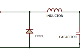
This tutorial shows you how to make a phone charger which uses any DC source (AAA/AA/SLA battery) as input and is efficient in terms of power utilization. We’ve been holding onto 7805 regulator IC from a very long time and hence a question may arise as to why we are not using the same this time. Well all these days we didn’t care about the efficiency since it was either a low current application or ones which didn’t run completely on battery but this time it is different. This time our aim is to create a device which runs on battery and needs to be utilizing the battery’s energy efficiently.
Wireless Water level control system
In Domestic and industrial applications we use water tanks to store water. Filling water in tank using water pump is quite common. When water inside the tank is over we have fill it by pumping water using an ac motor and after tank is filled with water we have stop the motor to. This is manual system means turning ON motor when tank is empty and turning it OFF when tank is full is manual. But now it is no more manual. Automatic motor on and off system based on tank water level is already available in market. This system is wired system and connecting circuit and arranging wires and circuit is little bit complex. In this system the biggest drawback is wired connections between control circuit and motor. So we have to use lengthy wires from top of the home to water supply unit and control circuit unit. If we want adapt this system for big building it will become too expensive and too complex.
Automobile Turn Signal

This is a very easy circuit . This can be employed in automobiles as a sequential indicate light. This circuit is constructed with the help of two ICs first one is a CMOS timer IC i.e. 555 timer and another one is the decade counter IC i.e. CD4017. In this circuit astable mode of the 555 timer IC is been used to trigger the counter. Also few other discrete components are used in the circuit.
Automated Car Lightning System
Our governement has made rules that at night times if any vehicle is approaching from opposite side headlights of our vehicle should be dimmed to avoid focusing of . light on the driver in opposite vehicle inorder to avoid accidents . But, we ignore this which is cause for many accidents at night times.
CD4001 IC -based Lighting System
CD 4001 is a quad, 2 input NOR gate IC made by Fairchild Semiconductors. It is a monolithic CMOS transistor based IC having efficient source and sink [[wysiwyg_imageupload::]]capabilities. Circuits that use this IC can be easily operated using battery as CD4001 is a low power consumption IC. A 14 pin DIP package, this IC can work at temperatures upto 1250. The circuit in this project is built around a commonly used CD4001 IC and few more discrete components. The circuit described can be used to decorate your Christmas tree with colorful lights. The blinking of LED’s will create a festive appearance which will enhance the Christmas mood.
Toggle flip flop using CD4013
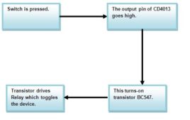
The circuit uses the CMOS dual D type flip flop CD4013 which contains two positive-edge triggered flip flop to toggle a load connected through a relay. Now [[wysiwyg_imageupload::]]with the help of a switch you can on the device once pressing it and off the device again using the same switch. In CD4013 each module is further equipped with a group of pin outs assigned as data, set, reset, clock input and a couple complementary output Q and Q(not) . As we know it has couple of output that change or toggle state as response to trigger applied to input terminals. In this circuit, one is wired in toggle mode while other is not used. Using this circuit we can easily control AC and DC appliances remotely through inexpensive low voltage cable and a standard push to on switch. This circuit can easily support a cable length of 25 meters.
4 Channel Programmable FM Remote Control

This is programmable FM remote control can be used for some specific applications. Phase Lock Loop (PLL) IC-567 is used in transmitter and receiver part as oscillator and filter respectively. It can operate/control any device / application from the distance of around 50 meter (this range can be increased up to 1-2 Km if good…
How to deal with an unknown stepper motor?
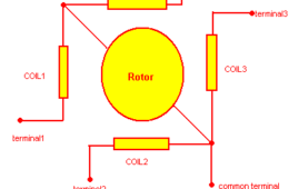
How to deal with any unknown stepper motor? This section deals with a special procedure that can be useful to find out the type of stepper motor, its terminals, its coil sequence, its step resolution and everything about stepper motor. if anyone have a steppe motor that doesn’t have any specifications then after going through this section…
Circuit Design: Reproduce Sound Signals Captured through a Microphone

This article discusses about a simple circuit that can reproduce the sound signals captured through a microphone on a loudspeaker. The microphone is a device which is used to capture sound signals and forms an essential part of most of the electronic gadgets. The microphone converts the sound signals in the environment to their corresponding electrical signals.
Circuit Design: Bass Separator

This article discusses how to design a simplest active bass separator circuit with design details. This is basically a low pass circuit which is used to separate out low frequency sounds from audio signals at audio play back devices. A simple loudspeaker is not capable of reproducing all the frequencies of the audible range. Different kinds of loudspeaker are available which can reproduce the sound at certain range of frequencies. The bass separator circuit alone is realized with the help of commonly available op-amp ICs. For demonstrating the working a bass beat is played in a mobile phone which is captured, amplified and mixed with a high frequency musical signal and is then again separated out using the bass separator circuit and reproduced in a loudspeaker. Read more to find out how the circuit is assembled and how it is tested and used.
DC Motor Control Using H Bridge

This article explains how one can change the direction and speed of mini DC motor using very simple circuit built using readily and easily available handy components. First we will see how we can change the direction of motor and then we will see how we can vary the speed of DC motor. Then I will explain very simple DC motor controller circuit that changes direction as well as varies the speed of DC motor. So let us start
Circuit Design: Automatic Gain Control

The amplifiers are devices which produces an output signal which is several times higher in amplitude than the input signals. The ratio of the amplitude of the output signal from an amplifier circuit to the amplitude of the input signal is called Gain. The amplifier circuits are normally designed for a fixed amount of gain. There are amplifiers with very low gain, like the amplifiers at the loudspeaker side of an audio device and also there are amplifiers with very high gain, like the amplifiers in the radio receivers or amplifiers at the microphone side of an audio device. The Automatic Gain Control (AGC) amplifiers are another category of amplifiers which can vary its gain according to the input signal level. They provide enough amplification for the weak signals and prevent strong signals from getting over amplified.
Joystick Based Dual DC Motor Controller Using OP-AMP

All you might have seen controlling a DC motor using joystick.Most of RC toys are DC motor operated and they are controlled using remote controlled joystick. There is a RF transmitter in the remote controlled joystick and in a toy, there is RF receiver that rotates DC motor forward (clockwise) and reverse (anticlockwise)The remote controlled robotic vehicles used in military applications also controlled using such joystick connected with laptop or computerUnmanned air vehicles like drone, quad copter etc used for air surveillance or aerial photography/videography are the best examples of joystick control
Electronic Circuit Designing: Modular Approach (Part 1)

A person’s inquisitiveness and curiosity can do wonders. It can open a realm of ideas and imaginations never thought before and create something worthwhile. When I was a child I used to read lot of electronic articles and magazines regularly. I’ve seen a lot of interesting circuits and tried as many of them as possible at that time. Whenever a new circuit catches my attention I can’t resist myself trying it out.
Electronic Circuit Designing: Modular Approach (Part 2)

Up to this point, we were developing the basic functions into specific functional blocks according to their requirements. Let’s take a look at what all functional blocks we have, it will give you an idea how far we advanced in the designing processEach of the blocks shown above can perform their own specified functions only. The entire blocks should perform together to give us a collective output. It will happen only when we connect the blocks together in the proper way. Next we are going to discuss how to connect these blocks together so that we have a complete block diagram for the device. From the entire discussion so far you might already have a picture about the way of connecting these blocks together. The IR light from the TV remote triggers the working of the device and who receives the IR light pulses from the TV remote, the IR photodiode.
Electronic Circuit Designing: Functional Block Designing (Part 3)

Step: 5) Design circuit for each functional block In this step we will be designing the circuit for individual blocks. The circuits required are simple and very basic circuit known to all; hence it won’t be such a big task. We are not designing anything new, but modifying the well-known basic circuits to suit our…
Electronic Circuit Designing: Multitasking With Circuits (Part 4)

Step: 8) Find reusable modules from the circuit diagram Whenever we do hardware designing, the first rule is to make it in modules that can be reusable. The modules that we make for this particular project may come useful in another project and hence reduce the development time for that project. Even if a…