Wireless Industrial intruder alarm system
Introduction
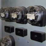
In industries, intruder alarms plays vital role in security. Existing industrial intruder alarms are wire based and alarms are placed on the wall. In this system a big alarm with loud sound works as alert. If some intruder enters then alarm activates and produces loud siren. Now consider another system. What if alarm is in hand of the security guards? There is only one sensor but there are several hand held simple alert alarms one with each security guard. Then it will become advance and impressive security system. But this is not possible with existing wire based system.
To achieve this we have to transmit one signal to several alarms at a time and for that we have to use RF wireless technology. The new thing in this project is, it uses only one intruder sensing system and activates lot of hand held alarms. Means only one transmitter activates several receivers at a time.
Description
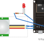
In this project LDR sensor is used to sense the intruder. When LDR sensor value changes the state (from low resistance to high resistance), the encoder data pins gets logic 1 (high) input. It sends that to receiver through transmitter module (434 Mhz). At receiver side when decoder data pins goes high it triggers IC555 and that triggers the alarm.
Required components and equipments:
Sr. no. Name of component Required quantity
1 RF Tx module(434Mhz) 1
2 RF Rx module(434Mhz) 1
3 HT12E 1
4 HT12D 1
5 LED 1
6 Resistor – 10KΩ (Quarter watt) 2
7 Resistor – 1MΩ (Quarter watt) 1
8 Resistor – 50KΩ (Quarter watt) 1
9 Resistor – 1KΩ (Quarter watt) 1
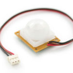
10 LDR 1
11 Resistor – 100 Ω (Quarter watt) 1
12 Transistor – 2n2222A 1
13 Resistor – 47K Ω (Quarter watt) 1
14 Capacitor – 0.1 µF 2
15 IC NE555 1
16 buzzer 1
17Battery – 9V
18Bread board
19connecting wires
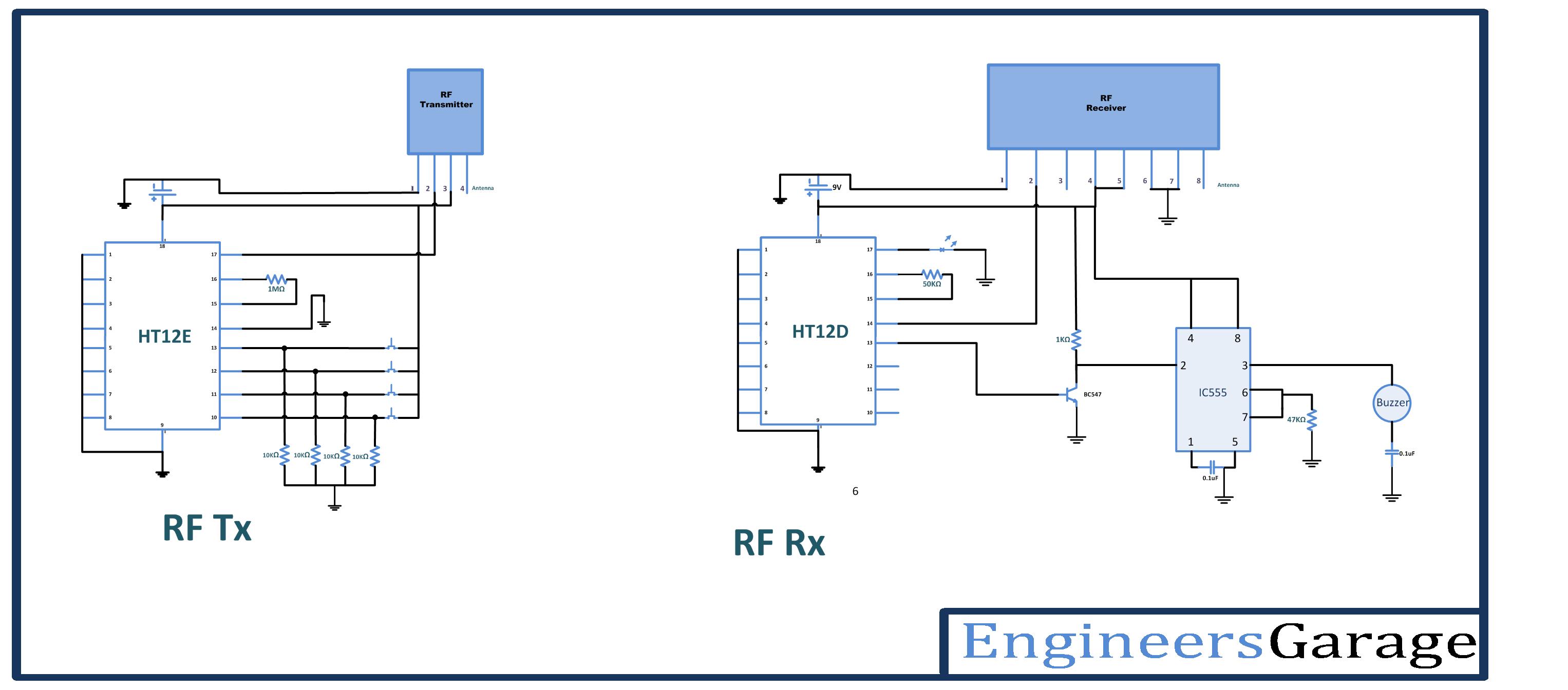
Circuit diagram:
Procedure:
Transmitter section:
Step1: connect the one LDR to data input pin 11 of HT12E, with pull up resistors of 10 KΩ.
Step2: connect 1MΩ resistor between 15 and 16 pins of HT12E.
Step3: connect 17 pin to the 2nd pin of RF transmitter, and 14 pin connect to the ground.
Step4: 1-8 pins of HT12E are address pins, all are connected to ground. Pin 18 is connected to Vcc and pin 9 is connected to ground.
Step5: Connect RF Tx module’s pin 1 to the ground, pin 3 to the Vcc and pin 4 to the antenna.
Receiver section:
Step1: connect pin 11 of decoder to base of the transistor. Connect transistor collector to the Vcc through 10Kohm resistor, and connect its emitter to the ground.
Step2: pins 4,8 of IC555 timer are connected to Vcc, and 1st pin to the ground.
Step3: 5th pin of IC555 is connected to ground through 0.1uF capacitor, and 2nd pin is connected to transistor collector.
Step4: short pins 6,7 of IC555 and connect to junction of resistor (47K) and capacitor (0.1 uF) as shown.
Step5: connect output pin (3rd) to buzzer positive terminal, and connect buzzer negative terminal to ground.
Step6: Connect 50KΩ resistor between 15 and 16 pins of HT12D.
Step7: Connect pin 14 to the 2nd pin of RF Rx module, and connect pin 17 to the LED indicator (it will glow when signal is received)
Step8: 1-8 pins of HT12D are address pins, all are connected to ground Connect pin 18 to Vcc and pin 9 to ground.
Step9: Connect RF Rx module’s 1, 6, 7 pins to the ground, pins 4 & 5 to the Vcc and pin 8 to the antenna.
Working:
1. The basic principle of this project is, triggering IC555 timer to activate the buzzer when LDR resistance becomes HIGH.
2. LDR resistance changes as per light falling on it. When shadow falls on it resistance become high. Based on this phenomenon here we are activating alarm.
3. In this project this circuit is dividing in to the two parts, LDR control at transmitter side and buzzer control at receiver side.
4. When shadow falls on LDR, its resistance increases, that changes logic state at input of encoder HT12E. so it transmits this data serially to receiver through 434 MHz ASK Tx module
5. At receiver side 434 MHz ASK Rx module gets this signal. It gives it to decoder HT12D. HT12D pin gives high output on same pin that is connected to alarm activating circuit.
6. The transistor gets high input so it conducts and gives low trigger input to IC555
7. IC555 generates high output pulse that sounds buzzer for few seconds. The time period depends upon connected RC components
8. The advantage of this project is we can place transmitter anywhere within the range, and number of alarms can be keep with so many guards. With only one transmitter we can activate many receivers.
Pictures:


While running the circuit it is required to take following precautions
Precautions:
1. Address lines status (high/low) should be same at both transmitter and receiver.
2. At transmitter 14th pin of HT12E should be connect to ground or connect a switch between ground and the 14th pin to reset the encoder.
3. In the transmitter circuit the resistor connected between 15 and 16 pins of HT12E should be between 750MΩ to 1MΩ. And at receiver side the resistor connected between 15 and 16 pins of HT12D should be between 30KΩ to 50KΩ.
4. Incase if you want to use any other battery, checkout the data sheet of HT12E/HT12D first.
You may also like:


Project Source Code
Project Source Code
###
//Program to###
Circuit Diagrams
Filed Under: Circuit Design, Electronic Projects

Questions related to this article?
👉Ask and discuss on EDAboard.com and Electro-Tech-Online.com forums.
Tell Us What You Think!!
You must be logged in to post a comment.