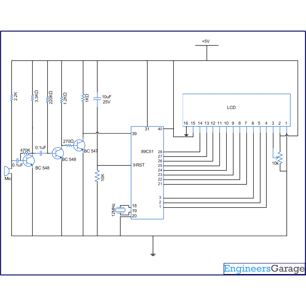
This article explains the concept behind interfacing a sound sensor with the 8051 microcontroller (AT89C51). This project increases the count by one every time a sound is produced. It works well with the sound of a clap. The number of claps is displayed on an LCD module. The circuit consists of four modules, namely, a sound sensor, an amplifying circuit, a control circuit and a display module. The code for interfacing the sound sensor with the MCU is written in C language.
The connections of different modules are shown in the circuit diagram. The data pins of the LCD are connected to port P2, while the control pins (RS, R/W & EN) are connected to pins 1-3 of port P1of AT89C51, respectively. The microcontroller receives sound pulses through the first pin of port P0.
A condenser microphone is used to sense the sound produced by the clap. This mic is connected to a two stage transistor amplifier. The mic output is thus amplified to a suitable level so that it can be detected at the TTL logic. A switching circuit made from a single transistor is also employed after the amplifier. The purpose of this circuit is to convert the analog signals into discrete digital signals, which are used as input for the MCU.
Project Source Code
###
// Program to count the number of clap #include<reg51.h> #define port P1 #define dataport P2 //Data Port for LCD #define sec 1000 sbit rs = port^0; sbit rw = port^1; sbit e = port^2; sbit sensor_input=P0^0; unsigned char str3[10]={' ',' ',' ',' ',' ',' ',' ',' ',' ',' '}; void delay(unsigned int msec) // Time delay function { int i,j ; for(i=0;i<msec;i++) for(j=0;j<1275;j++); } void lcd_cmd(unsigned char item) // Function to send command { dataport = item; rs= 0; rw=0; e=1; delay(1); e=0; return; } void lcd_data(unsigned char item) // Function to send data { dataport = item; rs= 1; rw=0; e=1; delay(1); e=0; return; } void lcd_data_string(unsigned char *str) // Function to send string { int i=0; while(str[i]!='�') { i++; } while(i>=0) { lcd_data(str[i]); i--; delay(10); } return; } void convert(int num) // Function to extract digits and send to LCD { int i=0; while(num>0) { str3[i]=(num%10)+48; num=num/10; i++; } str3[i]='�'; } void main() { int count=0; sensor_input=1; sensor_input=0; lcd_cmd(0x38); lcd_cmd(0x0e); lcd_cmd(0x01); while(1) { sensor_input=0; while(sensor_input==0); if(sensor_input==1) { lcd_cmd(0x01); count++; convert(count); lcd_cmd(0x82); lcd_data_string(str3); } } }###
Circuit Diagrams
Project Components
Filed Under: 8051 Microcontroller.


Questions related to this article?
👉Ask and discuss on Electro-Tech-Online.com and EDAboard.com forums.
Tell Us What You Think!!
You must be logged in to post a comment.