Engineers Garage

  • Electronic Projects & Tutorials
    • Electronic Projects
      • Arduino Projects
      • AVR
      • Raspberry pi
      • ESP8266
      • BeagleBone
      • 8051 Microcontroller
      • ARM
      • PIC Microcontroller
      • STM32
    • Tutorials
      • Audio Electronics
      • Battery Management
      • Brainwave
      • Electric Vehicles
      • EMI/EMC/RFI
      • Hardware Filters
      • IoT tutorials
      • Power Tutorials
      • Python
      • Sensors
      • USB
      • VHDL
    • Circuit Design
    • Project Videos
    • Components
  • Articles
    • Tech Articles
    • Insight
    • Invention Stories
    • How to
    • What Is
  • News
    • Electronic Product News
    • Business News
    • Company/Start-up News
    • DIY Reviews
    • Guest Post
  • Forums
    • EDABoard.com
    • Electro-Tech-Online
    • EG Forum Archive
  • DigiKey Store
    • Cables, Wires
    • Connectors, Interconnect
    • Discrete
    • Electromechanical
    • Embedded Computers
    • Enclosures, Hardware, Office
    • Integrated Circuits (ICs)
    • Isolators
    • LED/Optoelectronics
    • Passive
    • Power, Circuit Protection
    • Programmers
    • RF, Wireless
    • Semiconductors
    • Sensors, Transducers
    • Test Products
    • Tools
  • Learn
    • eBooks/Tech Tips
    • Design Guides
    • Learning Center
    • Tech Toolboxes
    • Webinars & Digital Events
  • Resources
    • Digital Issues
    • EE Training Days
    • LEAP Awards
    • Podcasts
    • Webinars / Digital Events
    • White Papers
    • Engineering Diversity & Inclusion
    • DesignFast
  • Guest Post Guidelines
  • Advertise
  • Subscribe

Clap Operated Remote Control for Devices

By Ashutosh Bhatt December 26, 2018


This circuit is based on two commonly used IC that is NE555 timer and CD4017 IC with few more components. 555 timer IC wired as an monostable oscillator. In this circuit NE555 monostable generates a clock for the circuit, which provide a oscillating wave to the output pin 3 of IC1.  Monostable or one short multivibrator has only one stable state and we have to trigger it externally to return it back to its original state.

CD4017 is a CMOS counter/ divider IC . It take clock signal from the clock input and turn on the 10 output in sequence, each time when it receives clock input pulses. It is the most popular IC and extremely useful in various project like Light Chaser, Matrix Die. In order to understand the working of IC one must know about its individual pin.


This circuit is very useful when you want to “ON” or “OFF” a device without moving from your place.

Another advantage of this circuit is that you cannot get any electrical shock as we did not have to use any mechanical switch. It will give you visual indication of the appliances also. You can also use this circuit to control the speed of your fan.

This circuit is based on two commonly used IC that is NE555 timer and CD4017 IC with few more components.

555 timer IC wired as an monostable oscillator. In this circuit NE555 monostable generates a clock for the circuit, which provide a oscillating wave to the output pin 3 of IC1.  Monostable or one short  multivibrator has only one stable state and we have to trigger it externally to return it back to its original state.And CD4017 is a CMOS counter/ divider IC . It take clock signal from the clock input and turn on the

10 output in sequence, each time when it receives clock input pulses. It is the most popular IC and  extremely useful in various project like Light Chaser, Matrix Die.

In order to understand the working of IC one must know about its individual pin. It has 3 input pin and 10 output pin and one is ground pin and another is used for power supply and one is Carry out pin. Pin diagram of CD4017 is shown below-


CD 4017


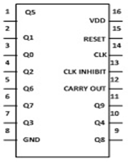
Fig. 1: Pin Diagram of CD4017 IC

1. Input pin-

a. Reset pin (pin 15) – It is used to reset the counter to zero. Like you want the counter to count up to third output then connect the fourth output to pin 15. Now after every third output it will automatically starts counting from zero.

b. Clock pin (pin14)- Whenever pin 14 goes high it will provide you the output. Like for first clock pulse pin 3 will provide you output similarly for next pulse pin 2 will provide output and so on. After 10 pulse it will again start from Q0 output.

c. Clock Inhibit pin (pin 13)- It is used to switch the counter “on” and “off”. When you want to switch off the counter then pin 13 should be high. If it is high it will ignore the clock pulse no matter how many times you press the switch means the count will not advance. In our circuit we have ground the pin 13.

2. Output pin (pin Q0- Q9)- It is used  to receive the output in sequential manner. Like for first pulse pin 3 will provide you the output and so on.

3. Ground pin (pin 8) and Supply pin (pin 16)- It is used to provide ground and power supply to the IC for its working.

4. Carry out pin (pin 12)- It is used to connect one or more CD4017 IC’s. Like if you want to add one more CD4017 IC then connect Pin 12 to Clock input of its successor. The carry pin of first CD4017 is connected to clock input of second and the carry pin of second is connected to the clock input of third and so on. In our circuit we have used only one IC that’s why we have left this pin.

Working of circuit-

When you clap in front of Mic the condenser microphone converts sound signals into electric signals. These signals are than provided to base of transistor T1 which in turn trigger the pin 2 of IC1. And the time duration for which output remain high can be calculated by the formula-

T = 1.1*R5*C4

Now output from pin 3 of IC1 is provided to CD4017 decade counter pin 14, which provide a clock pulse for the working of IC2. Here after receiving the clock input CD4017 starts its counter from zero (as it has inbuilt counter). And it advances one by one each time pin 14 goes high (as we clap in front of Mic). Like for first clap we get output from pin 2 that is Q1 and LED1 will glow and on second clap we get output from pin 4, LED2 will glow and LED1 become off and so on. You have to connect individual relay at every output (for demonstration I have used single relay).

With the help of this circuit you can control 10 individual devices.


Clap operated remote control circuit


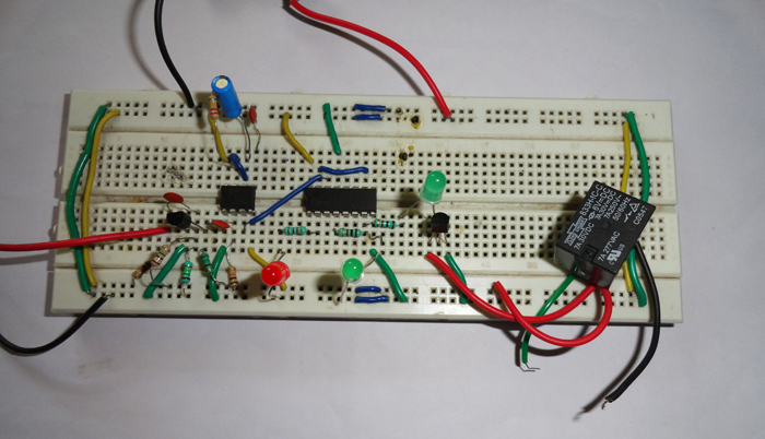
Fig. 2: Prototype of CD4017 IC based Clap Operated Remote Control System


Circuit Diagrams

Clap-operated-remote-control-for-devices_0

Project Components

  • The decline in Indian imports


Filed Under: Electronic Projects
Tagged With: clap, remote control
 

Next Article

← Previous Article
Next Article →

Questions related to this article?
👉Ask and discuss on EDAboard.com and Electro-Tech-Online.com forums.


Tell Us What You Think!! Cancel reply

You must be logged in to post a comment.

EE TECH TOOLBOX

“ee
Tech Toolbox: 5G Technology
This Tech Toolbox covers the basics of 5G technology plus a story about how engineers designed and built a prototype DSL router mostly from old cellphone parts. Download this first 5G/wired/wireless communications Tech Toolbox to learn more!

EE Learning Center

EE Learning Center
“engineers
EXPAND YOUR KNOWLEDGE AND STAY CONNECTED
Get the latest info on technologies, tools and strategies for EE professionals.

HAVE A QUESTION?

Have a technical question about an article or other engineering questions? Check out our engineering forums EDABoard.com and Electro-Tech-Online.com where you can get those questions asked and answered by your peers!


RSS EDABOARD.com Discussions

  • Redundant XORs
  • No Output Voltage from Voltage Doubler Circuit in Ansys Nexxim (Harmonic Balance Simulation)
  • Discrete IrDA receiver circuit
  • ISL8117 buck converter blowing up
  • I²C Ground Isolation with Series Battery Cells (ULIN13-01 + PIC18LF4520)

RSS Electro-Tech-Online.com Discussions

  • Help with finding unique wire lug(s)
  • Simple LED Analog Clock Idea
  • Kawai KDP 80 Electronic Piano Dead
  • Saga 1400sv vinyl cutter motherboard issue
  • using a RTC in SF basic

Featured – LoRa/LoRaWan Series

  • What is the LoRaWAN network and how does it work?
  • Understanding LoRa architecture: nodes, gateways, and servers
  • Revolutionizing RF: LoRa applications and advantages
  • How to build a LoRa gateway using Raspberry Pi
  • How LoRa enables long-range communication
  • How communication works between two LoRa end-node devices

Recent Articles

  • What is the LoRaWAN network and how does it work?
  • Understanding LoRa architecture: nodes, gateways, and servers
  • Revolutionizing RF: LoRa applications and advantages
  • How to build a LoRa gateway using Raspberry Pi
  • How LoRa enables long-range communication

EE ENGINEERING TRAINING DAYS

engineering

Submit a Guest Post

submit a guest post
Engineers Garage
  • Analog IC TIps
  • Connector Tips
  • Battery Power Tips
  • DesignFast
  • EDABoard Forums
  • EE World Online
  • Electro-Tech-Online Forums
  • EV Engineering
  • Microcontroller Tips
  • Power Electronic Tips
  • Sensor Tips
  • Test and Measurement Tips
  • 5G Technology World
  • Subscribe to our newsletter
  • About Us
  • Contact Us
  • Advertise

Copyright © 2025 WTWH Media LLC. All Rights Reserved. The material on this site may not be reproduced, distributed, transmitted, cached or otherwise used, except with the prior written permission of WTWH Media
Privacy Policy

Search Engineers Garage

  • Electronic Projects & Tutorials
    • Electronic Projects
      • Arduino Projects
      • AVR
      • Raspberry pi
      • ESP8266
      • BeagleBone
      • 8051 Microcontroller
      • ARM
      • PIC Microcontroller
      • STM32
    • Tutorials
      • Audio Electronics
      • Battery Management
      • Brainwave
      • Electric Vehicles
      • EMI/EMC/RFI
      • Hardware Filters
      • IoT tutorials
      • Power Tutorials
      • Python
      • Sensors
      • USB
      • VHDL
    • Circuit Design
    • Project Videos
    • Components
  • Articles
    • Tech Articles
    • Insight
    • Invention Stories
    • How to
    • What Is
  • News
    • Electronic Product News
    • Business News
    • Company/Start-up News
    • DIY Reviews
    • Guest Post
  • Forums
    • EDABoard.com
    • Electro-Tech-Online
    • EG Forum Archive
  • DigiKey Store
    • Cables, Wires
    • Connectors, Interconnect
    • Discrete
    • Electromechanical
    • Embedded Computers
    • Enclosures, Hardware, Office
    • Integrated Circuits (ICs)
    • Isolators
    • LED/Optoelectronics
    • Passive
    • Power, Circuit Protection
    • Programmers
    • RF, Wireless
    • Semiconductors
    • Sensors, Transducers
    • Test Products
    • Tools
  • Learn
    • eBooks/Tech Tips
    • Design Guides
    • Learning Center
    • Tech Toolboxes
    • Webinars & Digital Events
  • Resources
    • Digital Issues
    • EE Training Days
    • LEAP Awards
    • Podcasts
    • Webinars / Digital Events
    • White Papers
    • Engineering Diversity & Inclusion
    • DesignFast
  • Guest Post Guidelines
  • Advertise
  • Subscribe