Security systems work by measuring different physical parameters. One such parameter is sound. Every moving object produces sound and vibrations. These sounds and vibrations can be sampled, and the object can be identified. Sampling sound waves and training the system to distinguish between objects requires plenty of time.
For this tutorial, let’s take a simple sound sensor and interface it with an STM32 microcontroller. The sound sensor will recognize a clap sound and switches on the LED.
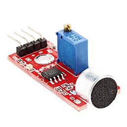 The sensor we are using is the most popular KY-038. On KY-038 sound sensor is placed in a circuit with other electrical components. Namely
- Differential amplifier
- Variable resistor (Potentiometer)
Why differential amplifier?
Sound sensor output voltage/signal is much lower than the standard microcontroller operating voltages (3.3 or 5 volts). To read the sound sensor’s output, it must be brought up to 3.3 or 5 volts, depending on the microcontroller operating voltage.
Many variants of KY-038 are available in the market, and various kinds of differential amplifiers are present on them. The most popular differential amplifier onboard is LM-393. Lm-393 is actually a comparator, but on our sensor board, the output voltage is pulled up. Moreover, the sensor module can output a digital as well as an analog signal.
Variable Resistor
A variable resistor is setting the threshold for sound recognition. The output of the variable resistor is input to the differential amplifier. The other input of the differential amplifier is the output of the sound sensor.
So how does it work?
A fixed voltage(threshold) is fed to one input of the comparator by a variable resistor. On any disturbance sound sensor outputs a voltage. The comparator compares the voltage threshold vs. disturbance. If disturbance greater than threshold amplify and output 1. If less than no output.
By rotating the knob of the variable resistor, we can adjust the sound detection level.
Project circuit:
Stm32f103 discovery development board is used to test the clap sensor. An led at the output will turn on for some time if clapped near the sensor.
Two GPIO pins of the STM32 microcontroller are required for this purpose. One as input to detect the clap signal from the sensor module and one as output to turn on the led. The circuit diagram of the project is below.
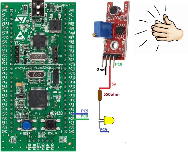
I used PC8 as the input pin and PC9 as the output pin. Led is pulled high in series with a 550-ohm resistor. Both the led and sensor module can be powered through stm32 discovery power output pins. The onboard regulator of stm32 can manage power for all three components.
Project code
The Code of the project is simple and straightforward. First, enable the clock for port-C of stm32. We must enable the clock because we are using two pins of port-C in our application. If this step is missed in any application, nothing will be seen at the output. So be sure to enable clocks for ports under use.
Next, GPIO pins PC8 and PC9 are declared. We need to set all the parameters for each pin. Pin 8 is declared as input, sampling speed is set to 50MHz, at last, no pull-up or down resistor is enabled.
PC9 only difference with respect to PC8 is it’s declared as an output pin. Push up and down resistors can be enabled depending on the circuit requirements. 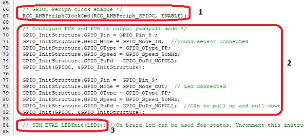 Another option is to use the onboard led of STM32 discovery. A single statement in the above code snap labeled 3 can be uncommented to use the onboard led. Behind the onboard led declaration function same code as written in box 2 is executed to declare the led.
Next comes the while loop. While1 loop executes continuously unless discovery is powered off. In the while loop first, if the statement is checking the status of the sensor output. If it is found high, the control enters if statement body.
Suppose statement body is composed of just two statements. The first statement sets the PC9 or led as high. The second statement is a for loop, which iterates 1000 times. These 1000 iterations produce a delay in milliseconds. This delay is very significant. It enables the person to see the led switching on and then back off visually. Led off statement is outside if statement.
During testing, it was found that it is impossible to see the led turning on and off without for loop delay. Led transition is so fast because of the operating frequency of the stm32.
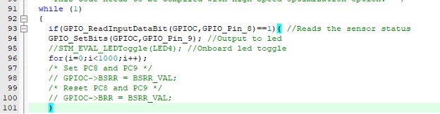
If you are using onboard led of stm32 discovery, you must uncomment the STM_EVAL_LEDToggle() instruction. LED togging can also be achieved if instead of GPIO_SetBits() directly GPIOC->BSSR and BSR are used. BSR and BSSR are output registers associated with ports of stm32. All the instructions are present in the above code.
Download full code from Github
The above concept can be applied in different applications, such as security systems, opening and closing doors, vehicle start theft, etc. The analog output of the sensor provides precise voltage change on disturbance. The analog feature can be used for precise sound differentiation. Working with analog features requires knowledge of ADC, which we will learn in the upcoming tutorials.
Let’s DIY the Project: Where to Purchase parts?
StM32 Discovery: From Mouser
Sound sensor: From Mouser
LED: From Mouser
Resistor: From Mouser
You may also like:


Filed Under: Electronic Projects, Microcontroller Projects, STM32, STM32.

Questions related to this article?
👉Ask and discuss on EDAboard.com and Electro-Tech-Online.com forums.
Tell Us What You Think!!
You must be logged in to post a comment.