In the previous tutorial, advantages of CoAP protocol over TCP/IP and UDP protocols in IoT applications were discussed. The CoAP protocol is specially designed for constraint devices and networks. In this project, the application of CoAP protocol in IoT will be demonstrated. In this project, an ESP8266 Wi-Fi modem will be configured as CoAP server and a laptop will be used as CoAP Client. Both Client and server will be co-located communicating through same Wi-Fi router so, the ESP board will act as a local server. The CoAP Client could send data to the server on a particular port with the help of browser add-on – Copper (Cu) CoAP user-agent. In fact, the Copper (Cu) itself will act as CoAP Client.
The ESP module working as server checks for the data received from the client on a particular port. The server listens at specified port with the specific service. The CoAP client discovers that service on the server IP address and the port. After finding the service, the client sends the GET or PUT request to access the server. The server responses (or acknowledges) to those requests and acts accordingly. In response to receiving packet and sending acknowledgement, the ESP modem switches on an LED as visual indication of successful Client-Server Communication.
This application is very useful as it demonstrates server/client communication over CoAP protocol. This application is beneficial in the field of IoT if the client and server have less memory resources and wants to communicate through request/response model.
It can be said that the IOT device designed in this project is a simple CoAP server with LED indicator. It is designed by interfacing an LED with the ESP-8266 Wi-Fi module. The Wi-Fi module as well as LED light are powered continuously with the help of a USB to Serial Converter. The Wi-Fi module needs to loaded with a firmware that could receive data over CoAP protocol and respond with an acknowledgement. The Arduino UNO is used to flash the firmware code on the ESP8266 module. The ESP module can also be flashed with code using a FTDI converter like CP2102. The firmware itself is written in the Arduino IDE.
Component Required –

Fig. 1: List of components required for CoAP protocol based Client Server Communication
Software Required –
• Copper (Cu)
• Arduino IDE
Block Diagram –

Fig. 2: Block Diagram of ESP8266 CoAP Server and Copper UDP Client Communication
Circuit Connections –
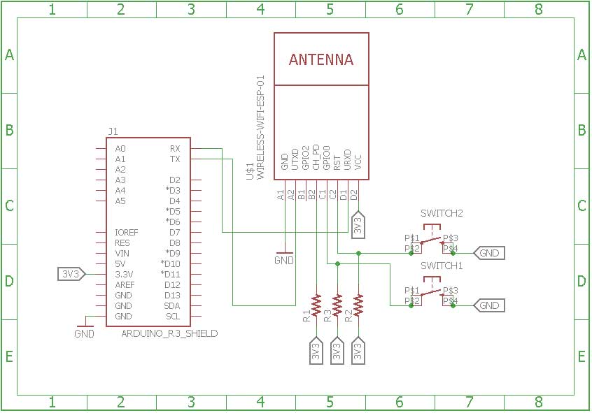
First of all, the ESP8266 board needs to be loaded with the firmware code. In this tutorial, the firmware code is written using Arduino IDE. It is loaded to the ESP8266 board using the Arduino UNO. A generic ESP8266 board is used in this project. This board does not have any bootstrapping resistors, no voltage regulator, no reset circuit and no USB-serial adapter. The ESP8266 module operates on 3.3 V power supply with current greater than or equal to 250 mA. So, CP2102 USB to serial adapter is used to provide 3.3 V voltage with enough current to run ESP8266 reliably in every situation.
The ESP8266 Wi-Fi Module is a self contained SOC with integrated TCP/IP protocol stack that can access to a Wi-Fi network. The ESP8266 is capable of either hosting an application or off loading all Wi-Fi networking functions from another application processor. Each ESP8266 module comes pre-programmed with an AT command set firmware. The module comes available in two models – ESP-01 and ESP-12. ESP-12 has 16 pins available for interfacing while ESP-01 has only 8 pins available for use. The ESP-12 has the following pin configuration –

Fig. 3: Table listing pin configuration of ESP8266 ESP-12 Wi-Fi Modem
The ESP-01 model is used in the project. The ESP-01 model has the following pin configuration –

Fig. 4: Table listing pin configuration of ESP8266 ESP-01 Wi-Fi Modem
The Chip Enable and VCC pins of the module are connected to the 3.3 V DC while Ground pin is connected to the common ground. The chip enable pin is connected to VCC via a 10K pull up resistor. The RESET pin is connected to the ground via a tactile switch where the pin is supplied VCC through a 10K pull up resistor by default. The Tx and Rx pins of the module are connected to the RX and TX pins of the Arduino UNO. The GPIO-0 pin of the module is connected to ground via a tactile switch where the pin is supplied VCC through a 10K pull up resistor by default. These pull-up resistors act as voltage divider circuit which protects the ESP8266 board from high voltage. The Arduino board operates at 5V as well as 3.3 V while ESP8266 operates at 3.3 V. Though the Arduino board itself is powered via its 3.3 V supply pin, this voltage divider circuit further adds protection from any voltage surge. The use of pull-up resistors increases the stability of the circuit. With these circuit connections, the Arduino board itself act as USB to Serial Adaptor. The circuit connections between the Arduino UNO and ESP8266 module for boot loading can be summarized as follow –

Fig. 5: Table listing circuit connections between Arduino and ESP8266 Modem
During compilation of the code, the GPIO0 and RESET switches must be pressed. For uploading program, the RESET switch must be released while the GPIO0 programming switch must be left pressed, so that the ESP can enter in programming mode. After uploading the code, the programming switch should also be released as well.
Write the firmware code in the Arduino IDE and connect the Arduino board with the PC via USB cable. Open Arduino IDE and go to Tools->Port and select the Arduino board (Arduino UNO). It may look like /dev/ttyABM0 (Arduino/Genuino Uno). Select the correct port name. The port name can be different in different IDE setups. Then Open Serial monitor in the Arduino IDE by navigating to Tools->Serial Monitor and set the baud rate to 115200 bauds per second. Pass ‘AT’ and ‘AT+GMR’ commands to test the connection between the Arduino and ESP-01 module. Try different settings for the ‘Line ending’ option of the serial monitor like Both NL & CR. Try different combinations until the ESP module starts interacting correctly with the serial monitor.
Download Python, PIP and ESPtool. Erase the pre-loaded firmware if the ESP module has any. Flash the firmware code to the ESP-01 module by writing the commands in serial monitor as instructed for the ESPtool. Check out the following link to write proper command for flashing the firmware code using ESPtool-
For uploading program, the RESET switch must be released while the GPIO0 programming switch must be left pressed. After loading the code, the programming switch should also be released as well. In this way, the firmware code can be loaded to the ESP8266 using the Arduino board as FTDI converter. It must be noted that every GND needs to be common to complete the circuit. The GPIO2 is alternative TX for bootloader mode.
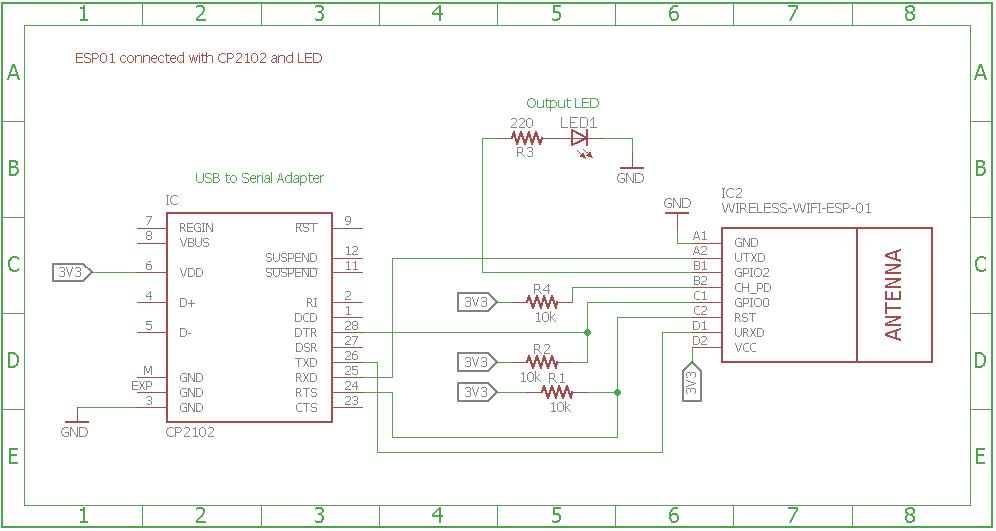
Remove the connections. Now the ESP module is ready to be installed in the project circuit. In the project circuit, the ESP8266 is interfaced with the CP2102 adapter and an LED.
The CP2102 is a single chip USB to UART Bridge. It is used to provide power supply to the ESP module. It can be used for boot loading as well. A CP2102 IC has the following pin configuration –

Fig. 6: Table listing pin configuration of CP2102 IC
Fig. 7: Table listing pin configuration of CP2102 IC
Fig. 8: Table listing pin configuration of CP2102 IC
The ESP board is connected to the CP2102 for boot loading mode and usage purpose. For boot loading, the ESP-01 TX pin is connected to RX pin of CP2102 and ESP’s RX pin is connected to the TX of CP2102 so that they both can send and receive the data. The ESP8266-01 needs 3.3 V power supply so ESP’s VCC is connected to the 3V3 of CP2102 and GNDs of both need to be connected to each other. The reset pin of ESP8266 along with 10k pull-up resistor (bootstrap resistor) is connected to the RTS pin of CP2102. The GPIO0 is a programming pin which is used to end the ESP-01 into programming mode. The GPIO0 along with 10K pull-up resistor is connected to DTR pin of CP2102. The CHPD pin of ES-01 is pulled-up with 10K resistor. The circuit connections between the ESP module and the CP2102 are summarized in the following table –

Fig. 9: Table listing circuit connections between ESP8266 ESP-01 Module and CP2102 IC
After connecting the ESP module with the CP2102 adapter, the adaptor must be connected to the PC and the ESP module must be loaded with the firmware code in the similar manner as is demonstrated with the Arduino.
After loading the code, the ESP module will automatically access the Wi-Fi point with the SSID given in the firmware. An LED is connected to the ESP module. The LED’s anode pin is connected to the GPIO2 with 220 ohm series resistor and cathode pin is connected to the GND. The ESP module is now ready to receive data over CoAP protocol via Wi-Fi Router and will control LED to indicate successful communication with the CoAP Client.

Fig. 10: Prototype of ESP8266 CoAP Server
ESP8266 CoAP Server Circuit
On the laptop, Copper (Cu) is used as a CoAP client. The client is installed as an add-on to Mozilla Firefox browser. It can be installed and added to Firefox using Mozilla addon.
 CoAP Agent on Mozilla Firefox")
Fig. 11: Screenshot of Copper (Cu) CoAP Agent on Mozilla Firefox
Copper (Cu) CoAP Agent for Mozilla Firefox
After installing the add-on, open the browser and enter the following URL – coap://<server domain name>:port. This will open the copper client which can request to the ESP8266 server and can get response from the server. The window should open with the IP address and port changed according to the network.
The following precautions must be taken care while assembling the circuit –
1) The ESP8266 needs 3.3V power to work, so do not provide 5V.
2) Some people say that ESP8266 does not have 5V tolerant Inputs but when Arduino was used as USB to Serial Adapter it successfully provided the serial communication. According to the datasheet of ESP8266, It has also written that the ESP8266 GPIOs can tolerate more power up to 6V.
3) If the error of espcomm_sync-failed.md is shown while uploading the firmware code, then first check the selected port on which the ESP module is connected and then check if the module is entering in bootloading mode or not. This can be checked by connecting RX and GND pin of converter to the TX and GND pin of ESP. Then open a terminal and check if the following message is received on serial window or not.
ets Jan 8 2017,rst cause:2, boot mode:(x,y).
4) Check if the module pins are getting proper voltage or not using multimeter.
5) If the module is working but it starts to burn after sometime then there can be an issue of current requirement. In that case, use an external power supply to provide 3.3V to ESP8266.
How the circuit works –
The ESP modem act as CoAP server in this setup. It is loaded with a firmware that can receive data on CoAP protocol and in response send back an acknowledgement on the same port. After loading the firmware code, the ESP8266 server starts listening with unique IP address and port (the port can be changed and it is defined in the code) with the defined services. The Laptop which is acting as CoAP Client sends the datagram using Copper (Cu) agent. The firmware code on the ESP modem light up an LED after successful communication with the CoAP Client.
In the firmware code of the ESP8266 based CoAP server, the Wi-Fi connection is initiated with the available router and the CoAP connection is setup using standard library functions. The libraries named Coap_server.h and ESP8266WiFi.h are imported in the ESP code for managing the CoAP connection and receiving data over it.
The server is configured to listen on the unique IP address with “1234” port using CoAP protocol. The Copper (Cu) client is also configured to send/receive the request/response from the server with the server domain name and port number. The server has a defined service “Room_light” which the client scan using the Discover mode. When the client discovers the service, the client is properly acknowledged with the service after the successful discovery process.
The Room_light service as a Resource acknowledgment can be seen from the copper agent as follow –
 CoAP Agent")
Fig. 12: Screenshot showing Discovering Services on Copper (Cu) CoAP Agent
Discovering Services on Copper (Cu) CoAP Agent
After discovering the service, Client selects the service and sends a PUT request with the message (0 or 1) in Outgoing window. The LED light switches ON or OFF at the server end on receiving the message 1 or 0 respectively. The client is also properly acknowledged whether the server has received the request or not. The client also sends the GET request or Observe command to get the current state of light. The server sends 0 or 1 light state accordingly.
 CoAP Agent")
Fig. 13: Screenshot showing Service Acknowledgement on Copper (Cu) CoAP Agent
In this way, the client communicates and accesses the service of server using CoAP protocol. There can be multiple services added at the server end which can be accessed at the client end. This application is the base for the communication process using CoAP protocol.
On the laptop side, the CoAP connection and data delivery is managed solely by the Copper Agent.
Programming Guide –
The ESP8266 modem is programmed to operate as UDP server. In the firmware code of the ESP8266 based CoAP server, the Wi-Fi connection is initiated with the available router and the CoAP connection is setup using standard library functions. The libraries named Coap_server.h and ESP8266WiFi.h are imported in the ESP code for managing the CoAP connection and receiving data over it. The ESP8266 client is connected to the local network by defining the SSID and Password of Wi-Fi router. The SSID and password of Wi-Fi access point are initialized in the Arduino code as follow –
const char* SSID_of_Router = “NOT UR WIFI”;
const char* PASSWORD_of_Router = “marketing”;
The following function is used to initiate the Wi-Fi connection –
WiFi.begin(SSID_of_Router, PASSWORD_of_Router);
After connecting ESP8266 to the Internet, it must configure to act as a CoAP server. The CoAP_server.h library is used for it. An instance of the server is defined and called in the setup function with the user-defined port to listen as follow –
//Create an instance of CoAP server
coapServercoap;
The CoAP connection is started by calling the start method on coap object as follow –
//Initiate the Connection of ESP8266 as a CoAP server & the port on which server is listening.
coap.start();
coap.start(1234);
The loop method is called. This will allow the server to continuously connect to the CoAP protocol –
coap.loop();
Now, the server is listening with CoAP protocol. This is the time to define the services at the server end so that client can access those services.
A service named – Room_light is defined in the light_control function (a callback function). Whenever the server receives the message from the client on this service, it responds accordingly. Like when it receives the PUT request with message ‘0’, the server light switches OFF and when it receives the request with 1, the light switches ON. Moreover, if the client wants to observe the state of the light at any time, the client sends the GET request or observe request to the server, the server upon receiving the request, responds it with the current light state (whether it is ON or OFF). Inside the callback function, the following code takes the PUT request from the client –
char p[packet->payloadlen + 1];
memcpy(p, packet->payload, packet->payloadlen);
p[packet->payloadlen] = NULL;
Serial.println(p);
The following code takes the GET or observe Request from the client –
//The server look for the observe flag or GET request from the client
if (obs == 1){
coap.sendResponse(Room_light);
}
else{
coap.sendResponse(ip, port, Room_light);
}
Check out the complete code from the code section for better understanding.
In the next tutorial, learn about Wireless Sensor Networks.
You may also like:


Project Source Code
### //Program to /* @Project: Browser_client_controls_Server_light @Hardware used: ESP8266-01 CP2102 or Arduino UNO (as a USB to Serial converter) LED & 220E resistor External Power supply to provide 3.3V to ESP8266 (Optional) @Brief Introduction: In this application, we have used ESP8266 as our CoAP server & Copper (Cu) as a CoAP client (it is supported with mozilla firefox browser.) The client sends GET, PUT request to the server and server controls the light on the basis of receiving PUT message. For more details, please refer our Article: Browser client controls Server light */ //Include Libraries #include//Include the ESP8266 library to connect the server to the WIFI #include //Include the CoAP server library to connect the server using CoAP protocol /* * Callback Function Declaration: This is a callback function, whenver server receives any get or put request, * the server responses accordingly through this function. * This Function takes the packet (Message), IP address & port of the CoAP client & observe the request on the particular service. */ void Light_control(coapPacket &packet, IPAddress ip, int port, int obs); //Create an instance of CoAP server coapServer coap; /* * Access point SSID & PASSWORD * Change this according to the network */ const char* SSID_of_Router = "NOT UR WIFI"; const char* PASSWORD_of_Router = "marketing"; //Connect LED to the GPIO2 of ESP8266 & for reading the led state at the client end, initialize the Variable for it. int light = 2; bool Light_state; //Define the Callback function void light_control(coapPacket *packet, IPAddress ip, int port, int obs) { char p[packet->payloadlen + 1]; memcpy(p, packet->payload, packet->payloadlen); p[packet->payloadlen] = NULL; Serial.println(p); String message(p); if (message.equals("0")) { digitalWrite(light, LOW); Serial.println("light is OFF"); } else if (message.equals("1")) { digitalWrite(light, HIGH); Serial.println("light is ON"); } char *Room_light = (digitalRead(light) > 0) ? ((char *) "1") : ((char *) "0"); //The server look for the observe flag or GET request from the client if (obs == 1){ coap.sendResponse(Room_light); } else{ coap.sendResponse(ip, port, Room_light); } } void setup() { yield(); //Start the serial Monitor at specified baud Rate as ESP8266 needs 115200 buad rate to communicate using serial Serial.begin(115200); //Initiate the connection of ESP8266 to the Router WiFi.begin(SSID_of_Router, PASSWORD_of_Router); Serial.println(" "); Serial.print("Connecting to...... "); Serial.println(SSID_of_Router); //Wait for the connection establishment while (WiFi.status() != WL_CONNECTED) { yield(); Serial.print("."); } Serial.println(""); //If ESP8266 Wi-Fi is connected to the Router then //we will see the IP address assigned to the ESP8266 Serial.println("WiFi connected"); Serial.println(WiFi.localIP()); pinMode(light, OUTPUT); digitalWrite(light, HIGH); Light_state = true; // add server url endpoints. // We can add multiple endpoint urls. coap.server(light_control, "Room_light"); //Initiate the Connection of ESP8266 as a CoAP server & the port on which server is listening. coap.start(); coap.start(1234); } void loop() { coap.loop(); delay(1000); } ###
Circuit Diagrams
Project Video
Filed Under: Featured Contributions, IoT, IoT tutorials, Tutorials
Filed Under: Featured Contributions, IoT, IoT tutorials, Tutorials

Questions related to this article?
👉Ask and discuss on EDAboard.com and Electro-Tech-Online.com forums.
Tell Us What You Think!!
You must be logged in to post a comment.