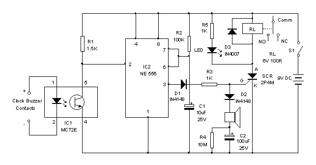
You can switch on a load such as Water pump automatically at the required time through this Clock Controlled Relay. It uses an ordinary clock to trigger the circuit to switch on the load. The load remains on till it is switched off manually.
The triggering signal is obtained from the DC voltage that develops in the terminals of clock buzzer when the alarm rings. In the terminals of the buzzer, around 2-3 volts DC develops when the alarm switches on. This voltage is tapped from the buzzer terminals to switch on the LED inside the Optocoupler IC MCT2E which has an LED and a Phototransistor inside. So when the LED inside the Optocoupler turns on, phototransistor forward biases and its collector go to ground potential.
The short duration monostable timer built around IC2 triggers when the phototransistor of IC1 conducts. The output pulse from IC2 triggers the SCR which turns on the Relay. The load connected through the Common and NO contacts of the relay then switches on.
SCR remains latched till its Anode voltage is removed by usingS1. The buzzer provided in the circuit gives a short beep when the SCR triggers.When current passes through the buzzer, C2 charges fully and the negative terminal of the buzzer becomes positive and it stops beeping further. A high value resistor R4 is provided to discharge the stored voltage from C2 to make the buzzer active again.
You can use a small low cost digital or ordinary table clock for the purpose. Remove the buzzer and connect the pins 1 and 2 of the Optocoupler to the buzzer terminals with correct polarity. Set the alarm time in the clock and at the correct time, the load will turns on. It can be switched off manually through S1.
Circuit Diagrams
Filed Under: Electronic Projects


Questions related to this article?
👉Ask and discuss on EDAboard.com and Electro-Tech-Online.com forums.
Tell Us What You Think!!
You must be logged in to post a comment.