Engineers Garage

  • Projects and Tutorials
    • Electronic Projects
      • 8051
      • Arduino
      • ARM
      • AVR
      • PIC
      • Raspberry pi
      • STM32
    • Tutorials
    • Circuit Design
    • Project Videos
    • Components
  • Articles
    • Tech Articles
    • Insight
    • Invention Stories
    • How to
    • What Is
  • News
    • Electronic Products News
    • DIY Reviews
    • Guest Post
  • Forums
    • EDABoard.com
    • Electro-Tech-Online
    • EG Forum Archive
  • Digi-Key Store
    • Cables, Wires
    • Connectors, Interconnect
    • Discrete
    • Electromechanical
    • Embedded Computers
    • Enclosures, Hardware, Office
    • Integrated Circuits (ICs)
    • Isolators
    • LED/Optoelectronics
    • Passive
    • Power, Circuit Protection
    • Programmers
    • RF, Wireless
    • Semiconductors
    • Sensors, Transducers
    • Test Products
    • Tools
  • EE Resources
    • DesignFast
    • LEAP Awards
    • Oscilloscope Product Finder
    • White Papers
    • Webinars
  • EE Learning Center
  • Women in Engineering

Clock using RTC DS12C887 & 8051 microcontroller (AT89C51) with alarm set function

By Himanshu Choudhary

DS12C887 is a real time clock (RTC) IC from Dallas Semiconductors. The RTCs provide precise time and date information. This article explains the making of a digital clock with alarm setting functionalities. RTC has been interfaced with AT89C51 to perform desired operations. This project is an improvement over Digital clock using RTC DS12C887 and 8051 microcontroller (AT89C51) with time set and has the alarm setting function also. The alarm setting function allows user to set the alarm. The clock time is displayed on the LCD.  The free source code for the program is available in C.


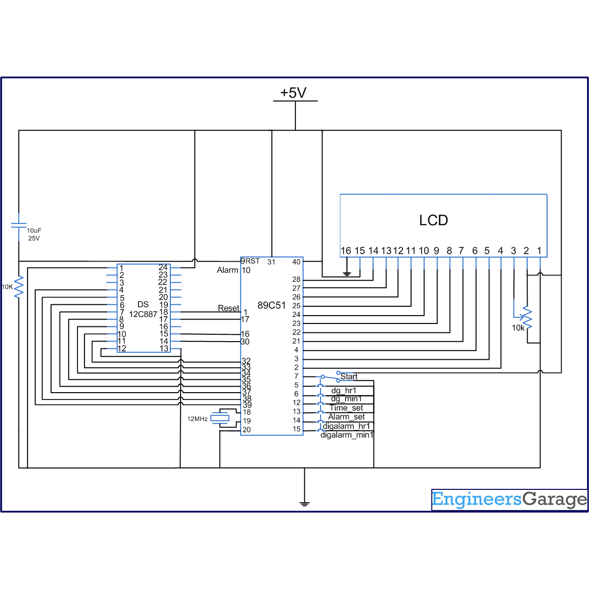
The circuit for interfacing the RTC and 16×2 LCD with the microcontroller 8051 is shown in the circuit diagram. Port P2 is set as data port for LCD to send the data on the LCD while port P0 is set as data port for the RTC DS12C887. This is used to extract the time, date and other information from the RTC. The pins of port P1 and P3 of the controller AT89C51 are used to provide the input signals for setting the time, alarm etc. They also provide control signals for the RTC and the LCD.

 
This project is an improved version of Digital clock using RTC DS12C887 and 8051 microcontroller (AT89C51) with time set with only difference that we can set alarm in it. It helps in understanding the concept of setting alarm in the RTC 12C887.  The program uses the two external interrupt 0 and 1 for setting the time and alarm respectively. For setting the time the pin P3^2 of the microcontroller 8051 is made low, which is the external interrupt 0. For alarm setting the pin P3^3 of the microcontroller is made low which is the external interrupt 1.
 
When any of the interrupts occur, the microcontroller stops its current operation and gets ready to set the time or alarm depending on the interrupt activated. The alarm can be set by using the pins digalarm_hr1 and digalarm_min1. The time can be set by using the pins dig_hr1 and dig_min1. When the alarm time matches the clock time, ‘Alarm’ is displayed on the LCD and the alarmport pin is set high for 10 sec. This pin can further be connected to a speaker or buzzer to sound the alarm.


Project Source Code

###

//Program for Digital Clock using RTC DS12C887 & 8051 microcontroller (AT89C51) with alarm set function
/*24 hr clock
set p3^3=0,then start=0 them set time by dig_hr1 & dig_min1, then remove p3^3 & start	*/
#include<reg51.h>
#include<absacc.h>
#define dataport P2	// Dataport for LCD
#define port P1
#define alarm P3

sbit reset = port^0;
sbit rs = port^1;
sbit rw = port^2;
sbit e = port^3;
sbit dig_hr1=port^4;
sbit dig_min1=port^5;
sbit digalarm_hr1=alarm^4;
sbit digalarm_min1=alarm^5;
sbit alarmport=alarm^0;
sbit start=port^6;

int  min1=0,hr1=0,alarmmin1=0,alarmhr1=0;
int min0=60,hr0=25;
unsigned char sec0=60,min00,hr00,hr,min,sec,alarmmin,alarmhr;

void delay(unsigned int msec )
{
	int i ,j ;
	for(i=0;i<msec;i++)
	for(j=0; j<1275; j++);
}

unsigned char num(int d)
{
	switch(d)
	{
		case 0:{
				return 0x00;
				break;
				}
		case 1:{
				return 0x01;
				break;
				}
		case 2:{
				return 0x02;
				break;
				}
		case 3:{
				return 0x03;
				break;
				}
		case 4:{
				return 0x04;
				break;
				}
		case 5:{
				return 0x05;
				break;
				}
		case 6:{
				return 0x06;
				break;
				}
		case 7:{
				return 0x07;
				break;
				}
		case 8:{
				return 0x08;
				break;
				}
		case 9:{
				return 0x09;
				break;
				}
		case 10:{
				return 0x10;
				break;
				}
		case 11:{
				return 0x11;
				break;
				}
		case 12:{
				return 0x12;
				break;
				}
		case 13:{
				return 0x13;
				break;
				}
		case 14:{
				return 0x14;
				break;
				}
		case 15:{
				return 0x15;
				break;
				}
		case 16:{
				return 0x16;
				break;
				}
		case 17:{
				return 0x17;
				break;
				}
		case 18:{
				return 0x18;
				break;
				}
		case 19:{
				return 0x19;
				break;
				}
		case 20:{
				return 0x20;
				break;
				}
		case 21:{
				return 0x21;
				break;
				}
		case 22:{
				return 0x22;
				break;
				}
		case 23:{
				return 0x23;
				break;
				}
		case 24:{
				return 0x24;
				break;
				}
		case 25:{
				return 0x25;
				break;
				}
		case 26:{
				return 0x26;
				break;
				}
		case 27:{
				return 0x27;
				break;
				}
		case 28:{
				return 0x28;
				break;
				}
		 case 29:{
				return 0x29;
				break;
				}
		case 30:{
				return 0x30;
				break;
				}
		case 31:{
				return 0x31;
				break;
				}
		case 32:{
				return 0x32;
				break;
				}
		case 33:{
				return 0x33;
				break;
				}
		case 34:{
				return 0x34;
				break;
				}
		case 35:{
				return 0x35;
				break;
				}
		case 36:{
				return 0x36;
				break;
				}
		case 37:{
				return 0x37;
				break;
				}
		case 38:{
				return 0x38;
				break;
				}
		case 39:{
				return 0x39;
				break;
				}
		case 40:{
				return 0x40;
				break;
				}
		case 41:{
				return 0x41;
				break;
				}
		case 42:{
				return 0x42;
				break;
				}
		case 43:{
				return 0x43;
				break;
				}
		case 44:{
				return 0x44;
				break;
				}
		case 45:{
				return 0x45;
				break;
				}
		case 46:{
				return 0x46;
				break;
				}
		case 47:{
				return 0x47;
				break;
				}
		case 48:{
				return 0x48;
				break;
				}
		case 49:{
				return 0x49;
				break;
				}
		case 50:{
				return 0x50;
				break;
				}
		case 51:{
				return 0x51;
				break;
				}
		case 52:{
				return 0x52;
				break;
				}
		case 53:{
				return 0x53;
				break;
				}
		case 54:{
				return 0x54;
				break;
				}
		case 55:{
				return 0x55;
				break;
				}		 
		case 56:{
				return 0x56;
				break;
				}
		case 57:{
				return 0x57;
				break;
				}
		case 58:{
				return 0x58;
				break;
				}
		case 59:{
				return 0x59;
				break;
				}
	}
}

void lcd_cmd(unsigned char item)
{
	dataport = item;
	rs= 0;
	rw=0;
	e=1;
	delay(1);
	e=0;
	return;
}

// DATA SENDING FUNCTION
void lcd_data(unsigned char item)
{
	dataport = item;
	rs= 1;
	rw=0;
	e=1;
	delay(1);
	e=0;
	return;
}

void lcd_data_string(unsigned char *str)
{
	int i=0;
	while(str[i]!='')
	{
		lcd_data(str[i]);
		i++;
		delay(1);
	}
	return; 
}

void lcd_data_int(int time_val)
{
	int int_amt;
	int_amt=time_val/10;
	lcd_data(int_amt+48);
	int_amt=time_val%10;	 
	lcd_data(int_amt+48);
}

void lcd()			// Function to initialize LCD
{
	lcd_cmd(0x38);		  
	delay(5);
	lcd_cmd(0x0C);        
	delay(5);
	lcd_cmd(0x80);
	delay(5);
}

void set_rtc_time( int q)  
{
	XBYTE[10]=0x20;
	XBYTE[11]=0x82;
	XBYTE[0]=0x00;
	if(q==1)
	{
		XBYTE[2]=min;
		XBYTE[4]=hr;
	}
	XBYTE[7]=0x01;
	XBYTE[8]=0x01;
	XBYTE[9]=0x10;
	XBYTE[1]=0xff;
	if(q==2)
	{
		XBYTE[3]=alarmmin;
		XBYTE[5]=alarmhr;
	}
	XBYTE[11]=0x22;
}

//function to set hours
void set_hr1(char a,int b)
{
	if(b==1)
	{
		hr1++;
		if(hr1>23)
		hr1=0;
		lcd_cmd(a);
		lcd_data_int(hr1);
		lcd_data(':');
	}
	else
	{
		alarmhr1++;
		if(alarmhr1>23)
		alarmhr1=0;
		lcd_cmd(a);
		lcd_data_int(alarmhr1);
		lcd_data(':');
	}
}

//function to set minute
void set_min1(char a,int b)
{
	if(b==1)
	{
		min1++;
		if(min1>59)
		min1=0;
		lcd_cmd(a);
		lcd_data_int(min1);
	}
	else
	{
		alarmmin1++;
		if(alarmmin1>59)
		alarmmin1=0;
		lcd_cmd(a);
		lcd_data_int(alarmmin1);
	}
}

void set_time()	interrupt 0
{
	reset=0;
	lcd_cmd(0x01);
	if(start==0)
	{
		lcd_data_string("SET TIME");
		lcd_cmd(0x8A);
		lcd_data_int(hr1);
		lcd_data(':');
		lcd_data_int(min1);
		lcd_cmd(0xc0);
		while(start==0)
		{
			delay(10);
			if(dig_hr1==0)
			set_hr1(0X8a,1);
			if(dig_min1==0)
			set_min1(0X8d,1);	 
		}
	}
	lcd_cmd(0x01);
	hr=num(hr1);
	min=num(min1);
	set_rtc_time(1);
	lcd_cmd(0x01);
	lcd_cmd(0x80);
	lcd_data_string("TIME:");
	hr0=25;
	min0=60;
}

void set_alarm()	interrupt 2					 // Time set function
{
	reset=0;
	lcd_cmd(0x01);
	if(start==0)
	{
		lcd_data_string("SET ALARM");
		lcd_cmd(0x8b);
		lcd_data_int(alarmhr1);
		lcd_data(':');
		lcd_data_int(alarmmin1);
		while(start==0)
		{
			delay(10);
			if(digalarm_hr1==0)
			set_hr1(0X8b,2);
			if(digalarm_min1==0)
			set_min1(0X8e,2);	 
		}
	}
	lcd_cmd(0x01);
	alarmhr=num(alarmhr1);
	alarmmin=num(alarmmin1);
	set_rtc_time(2);
	lcd_cmd(0x01);
	lcd_cmd(0x80);
	lcd_data_string("TIME:");
	hr0=25;
	min0=60;
}

bcdconv(unsigned char mybyte)
{
	unsigned char x,y;
	x=	mybyte & 0x0F;
	x=x | 0x30;
	y= mybyte & 0xF0;
	y=y>>4;
	y=y | 0x30;
	lcd_data(y);
	lcd_data(x);
}

void alarm1() 							  // Function to check alarm 
{
	reset=0;
	reset=1;
	lcd_cmd(0xc3);
	lcd_data_string("alarm");
	delay(100);
	lcd_cmd(0xc3);
	lcd_data_string("     ");
}

void read_rtc_display() 		 //Function to read RTC
{ 
	hr00=num(hr0);
	min00=num(min0);
	XBYTE[11]=0x22;
	hr=XBYTE[4];
	lcd_cmd(0x87);
	min=XBYTE[2];
	sec=XBYTE[0];
	if(hr!=hr00)
	{
		lcd_cmd(0X87);
		bcdconv(hr);
		lcd_data(':');
		hr0=hr;
	}
	if(min!=min00)
	{
		lcd_cmd(0X8A);
		bcdconv(min);
		lcd_data(':');
		min0=min;
	}
	if(sec!=sec0)
	{
		lcd_cmd(0x8D);
		bcdconv(sec);
		sec0=sec;
	}
}

void main()
{
	reset=1;
	lcd();
	XBYTE[10]=0x20;
	lcd_cmd(0x01);
	IE=0x85;
	lcd_cmd(0x80);
	lcd_data_string("TIME:");
	while(1)
	{
		read_rtc_display();
		if(alarmhr ==hr && alarmmin ==min )
		{
			alarm1();
		}
	}
}

###


Circuit Diagrams

Circuit-Diagram-Clock-Using-RTC-DS12C887-8051-Microcontroller-AT89C51-Alarm-Set-Function

Project Components

  • AT89C51 Microcontroller
  • LCD
  • RTC DS12C887

Project Video


Filed Under: 8051 Microcontroller
Tagged With: 8051, clock, ds12c887, lcd, microcontroller
 

Questions related to this article?
👉Ask and discuss on EDAboard.com and Electro-Tech-Online.com forums.


Tell Us What You Think!! Cancel reply

You must be logged in to post a comment.

HAVE A QUESTION?

Have a technical question about an article or other engineering questions? Check out our engineering forums EDABoard.com and Electro-Tech-Online.com where you can get those questions asked and answered by your peers!


Featured Tutorials

  • Designing Gate Driver Circuit and Switching Mechanism for Modified Sine Wave Inverter – (Part 9/17)
  • Completing Modified Sine Wave Inverter Design with Full Bridge Circuit and Step Up Transformer – (Part 10/17)
  • Designing an Offline UPS – Part (12 /17)
  • How to reduce Switching Time of a Relay – (Part 15/17)
  • Testing MOSFET – (Part 16/17)
  • Driving High Side MOSFET using Bootstrap Circuitry – (Part 17/17)

Stay Up To Date

Newsletter Signup

Sign up and receive our weekly newsletter for latest Tech articles, Electronics Projects, Tutorial series and other insightful tech content.

EE Training Center Classrooms

EE Classrooms

Recent Articles

  • Designing Gate Driver Circuit and Switching Mechanism for Modified Sine Wave Inverter – (Part 9/17)
  • Completing Modified Sine Wave Inverter Design with Full Bridge Circuit and Step Up Transformer – (Part 10/17)
  • Designing an Offline UPS – Part (12 /17)
  • How to reduce Switching Time of a Relay – (Part 15/17)
  • Testing MOSFET – (Part 16/17)

Most Popular

5G 555 timer circuit 8051 ai Arduino atmega16 automotive avr dc motor display Electronic Part Electronic Parts Fujitsu ic infineontechnologies integratedcircuit Intel IoT ir lcd ldr led maximintegratedproducts microchip microchiptechnology Microchip Technology microcontroller microcontrollers mosfet motor powermanagement Raspberry Pi remote renesaselectronics Research robot samsung semiconductor sensor software STMicroelectronics switch Technology vishayintertechnology wireless

RSS EDABOARD.com Discussions

  • Do you use C++ for device drivers in embedded systems?
  • MAX5389 resetting by noise
  • Help with Verilog replicate operator
  • Verilog/SV: Using an array as a set of individual registers and not RAM
  • How did they made the old manuals or magazines sketches?

RSS Electro-Tech-Online.com Discussions

  • Relaxation oscillator with neon or...
  • MOSFET gets hot and burns
  • LCD display on PICDEM 2 Plus board
  • software PWM
  • Positive and negative sides of voltage source
Engineers Garage
  • Analog IC TIps
  • Connector Tips
  • DesignFast
  • EDABoard Forums
  • EE World Online
  • Electro-Tech-Online Forums
  • Microcontroller Tips
  • Power Electronic Tips
  • Sensor Tips
  • Test and Measurement Tips
  • 5G Technology World
  • About Us
  • Contact Us
  • Advertise

Copyright © 2022 WTWH Media LLC. All Rights Reserved. The material on this site may not be reproduced, distributed, transmitted, cached or otherwise used, except with the prior written permission of WTWH Media
Privacy Policy | Advertising | About Us

Search Engineers Garage

  • Projects and Tutorials
    • Electronic Projects
      • 8051
      • Arduino
      • ARM
      • AVR
      • PIC
      • Raspberry pi
      • STM32
    • Tutorials
    • Circuit Design
    • Project Videos
    • Components
  • Articles
    • Tech Articles
    • Insight
    • Invention Stories
    • How to
    • What Is
  • News
    • Electronic Products News
    • DIY Reviews
    • Guest Post
  • Forums
    • EDABoard.com
    • Electro-Tech-Online
    • EG Forum Archive
  • Digi-Key Store
    • Cables, Wires
    • Connectors, Interconnect
    • Discrete
    • Electromechanical
    • Embedded Computers
    • Enclosures, Hardware, Office
    • Integrated Circuits (ICs)
    • Isolators
    • LED/Optoelectronics
    • Passive
    • Power, Circuit Protection
    • Programmers
    • RF, Wireless
    • Semiconductors
    • Sensors, Transducers
    • Test Products
    • Tools
  • EE Resources
    • DesignFast
    • LEAP Awards
    • Oscilloscope Product Finder
    • White Papers
    • Webinars
  • EE Learning Center
  • Women in Engineering