This tutorial is going to take you through how to make a system which senses which colour is most prominent in the background, using the same principal an LCD screen uses to display colour. It’s is relatively simple to make, while the code is of moderate length. The output is in the form of a hexadecimal value, which is the accepted norm for representing colours, and can be typed in to any picture editing application like paint or Photoshop to give you the resulting colour on your screen.
Components Required:
1. Arduino with AVR atmega32 microcontroller (or some other equivalent microcontroller of your choice.
2. Photodiodes x3
3. Red, Green and blue cellophane/translucent paper
4. Perf board
5. Cardboard
6. Resistors
7. Switch
How does an LCD monitor display colour?
Each pixel on any LCD or LED monitor you own consists of three ‘sub-pixels’ which are nothing but red, green and blue lights. These lights combined make up the 16.9 million colours that are commonly advertised. Each LED is given a voltage value from 0 to 256,to adjust its brightness from completely lit to unlit. This corresponds to an 8-bit hexadecimal number. Since there are three leds, it take 3×8=24 bits to completely represent one pixel, or one colour. The above explanation forms the base of how we are going to make the colour detector.
Working Principle
· Each photodiode is put behind a thin sheet of coloured cellophane/translucent paper. The cellophane paper makes sure that only light of that particular colour falls through to the photodiode sensors below.
· First, white light from a considerably bright source (sunlight works better is shone on the three coloured cellophane papers, and the readings from the three sensors are noted ( sayr,g, and b for the red ,green , and blur sensors respectively). These readings give the maximum value of red, green and blue, thus defining the benchmarks.
· Now, light from the source whose colour is to be determined is shone on to the sensors. The readings from each sensor are noted.
· The readings obtained are compared with the calibrated readings, and scaled to 256.
· Hence, we get three values from 0 to 256 of red green and blue, which completely describes the colour being measured.
· In case the sensors need to be recalibrated, the switch is pressed down in the presence of a source of white light.
Block Diagram

Fig. 1: Block Diagram of Arduino based Color Detector
Procedure and guidelines
Step 1- Prepare the three coloured cellophane paper covering
Use cardboard or hard paper to make the shell which resembles three boxes attaché to each other open on two opposite sides. On one of these sides attach the translucent paper and on the other side place the sensitive side of the photodiode.

Fig. 2: Image of Cellopane Paper Covers
(above) outer shell of covering

Fig. 3: Image of RGB Sample Colors
(above) after translucent paper is attached

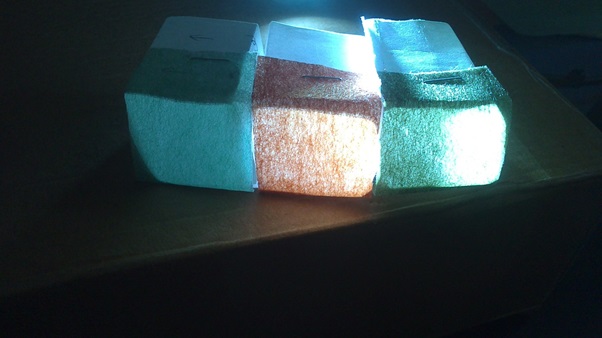
Fig. 4: Image of RGB Sample Colors with White Backlight
(above) before moving forward, make sure that light can easily pass through the paper
Prototyping on Breadboard
Step 2- Connect the external components
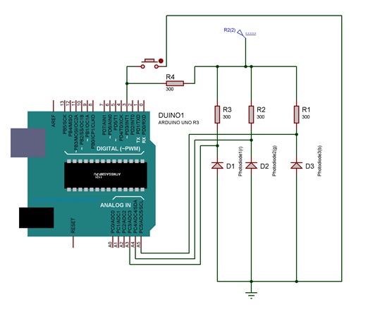
Connect the resistors, photodiodes and switches as shown in the circuit diagram. You can use a breadboard ,perfboard, or even a PCB.

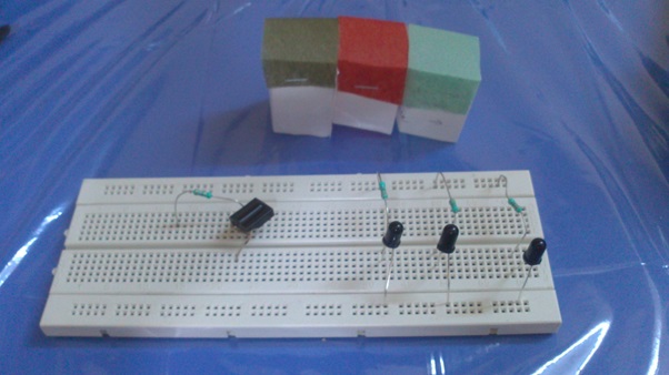
Fig. 5: Image of Color Source build on Breadboard
(above) external components connected

Fig. 6: Image of Color Source build on Breadboard with Color Samples
(above) Covering placed over photodiodes
Step 3- Make the connections with the arduino
Using female jumper wires, make the required connections to the 5v pin, ground pin and the various port pins of the arduino as shown in the circuit diagram.

Fig. 7: Prototype of Arduino based Color Sensor
(above) connections made to arduino via jumper wires

Fig. 8: Final Prototype of Arduino based Color Sensor
(above) finished circuit
Step 4-Burn the code into the arduino
Copy and paste the given code into the arduino IDE and burn it on to the arduino using A-B USB connection wire.
Guidelines:
· Since the photodiodes are highly directional, make sure they are all kept parallel to each other and facing upwards the same way.
· If you want to adjust the sensitivity , a potentiometer or rheostat can be connected in series with the photodiode instead of the resistor. The lower the resistance the higher the sensitivity
· Make sure a resistor is connected between the power supply and pin 3 to avoid a harmful short circuit.
· The cellophane/translucent paper should be light as darker paper will render the sensors obsolete.
· The arduino should take multiple readings from the sensors and filter the highest reading. This is because the photodiodes are highly directional and hence there is sometimes a reading of zero. (Check more arduino projects)
Code Algorithm
1. Initialize the input pins and output pins.
2. Check the state of the switch pin (pin3) if it is high, take the reading if it is zero, calibrate the sensors.
3. To take readings, store three to four values in consecutive intervals of 5ms from each sensor and take the highest value as the reading.
4. Repeat for the other two sensors.
5. To calibrate, take readings from all three sensors and store the values as calibration constants.
6. To obtain the output value divide the reading from each sensor by its calibration constant and multiply by 256.
7. Print the output value on the serial monitor.
Project Source Code
###
int red=A3;
int green=A4;
int blue=A5;
int choice=3;
void setup()
{
Serial.begin(9600);
pinMode(A3,INPUT);
pinMode(A4,INPUT);
pinMode(A5,INPUT);
pinMode(3,INPUT);
intrconst,gconst,bconst,r,g,b;
}
void loop()
{
if(choice==0){
rconst=takereading(red);
bconst=takereading(blue);
gconst=takereading(green);
}
if( choice==1){
r=takereading(red);
b=takereading(blue);
g=takereading(green);
}
Serial.println("r=",r,"g=",g,"b=",b);
}
inttakereading(int pin){
int r1,r2,r3;
r1=analogRead(pin);
delay(5);
r2=analogRead(pin);
delay(5);
r3=analogRead(pin);
reading=max(r1,r2,r3);
return reading;
}
###
Circuit Diagrams
Filed Under: Electronic Projects


Questions related to this article?
👉Ask and discuss on Electro-Tech-Online.com and EDAboard.com forums.
Tell Us What You Think!!
You must be logged in to post a comment.