This project demonstrates the use of a accelerometer as a computer mouse, but first what is an accelerometer? Its a device that can measure acceleration and the pull of gravity. There are multiple ways of doing this, the particular one I’m using works with the capacitive method. Inside the chip is a capacitor with an extra plate in the middle that can move. As you know the closer the objects are together the bigger the capacitance, the circuit inside the chip measures the capacitance difference between the two plates and the middle one. Finally the circuit coverts this in to a analog signal between 0V and 3.3V. All of this is small enough to fit in to a small SMD chip.

Fig. 1: Image of Accelerometer based Wireless Mouse
PROTOCOL
Generally when ever there is a case of interfacing the embedded system with compueter software there is one important thing that is to be followed strictly and that is protocol. Protocol is a set of rules regulations and syntax that is to be followed so as to achieve successful communication between transmitter and receiver i.e. PC side.
Normally there is set of some commands with data in between them, when received by the software, it checks whether it is correct or not, if found correct the communication is established and data transfer takes place. Protocol plays an important role in communication.

Fig. 2: Prototype of Accelerometer based Wireless Mouse
Description
DESCRIPTION
The accelerometer used in this project is ADXL335 . It has two sensors inside the chip, each facing at 90° to each other providing the X and Y axis. This is perfect for a mouse. In this case we are using it to detect the angle of the mouse. When the mouse is completely horizontal bough X and Y have 0G applied to them, but when we tilt the mouse the gravitational pull starts to cause force on the axis. But we wanted to move the mouse cursor using this. So we put on a PIC microcontroller, connect all the outputs to the ADCs and send the data over to the PC.
PIN DESCRIPTION
VCC :- 5v DC or 3.3v DC
GND :- Connected to negative
Xout :- gives the variable analog voltage output in x axis
Yout:- gives the variable analog voltage output in y axis
Zout :- gives the variable analog voltage output in z axis
St :- used to select the accuracy (generally not connected)
Project Source Code
### #include <mega8.h> #include <delay.h> #include <stdio.h> #define ADC_VREF_TYPE 0xE0 //=============================================================================== //ROUTINE TO TRANSMIT INTEGER void txint(unsigned int send) { UDR=send; // data store in UDR while(!(UCSRA & (1<<UDRE))); // wait for empty UDR } //=============================================================================== unsigned char read_adc(unsigned char adc_input) { ADMUX=adc_input | (ADC_VREF_TYPE & 0xff); // Delay needed for the stabilization of the ADC input voltage delay_us(10); // Start the AD conversion ADCSRA|=0x40; // Wait for the AD conversion to complete while ((ADCSRA & 0x10)==0); ADCSRA|=0x10; return ADCH; } // Declare your global variables here void main(void) { int x,y,z,sx,sy; int button; // Declare your local variables here // Input/Output Ports initialization // Port B initialization // Func7=In Func6=In Func5=In Func4=In Func3=In Func2=In Func1=In Func0=In // State7=T State6=T State5=T State4=T State3=T State2=T State1=T State0=T PORTB=0x00; DDRB=0x00; // Port C initialization // Func6=In Func5=In Func4=In Func3=In Func2=In Func1=In Func0=In // State6=T State5=T State4=T State3=T State2=T State1=T State0=T PORTC=0x00; DDRC=0x00; // Port D initialization // Func7=In Func6=In Func5=In Func4=In Func3=In Func2=In Func1=In Func0=In // State7=T State6=T State5=T State4=T State3=T State2=T State1=T State0=T PORTD=0x00; DDRD=0x00; // Timer/Counter 0 initialization // Clock source: System Clock // Clock value: Timer 0 Stopped TCCR0=0x00; TCNT0=0x00; // Timer/Counter 1 initialization // Clock source: System Clock // Clock value: Timer1 Stopped // Mode: Normal top=0xFFFF // OC1A output: Discon. // OC1B output: Discon. // Noise Canceler: Off // Input Capture on Falling Edge // Timer1 Overflow Interrupt: Off // Input Capture Interrupt: Off // Compare A Match Interrupt: Off // Compare B Match Interrupt: Off TCCR1A=0x00; TCCR1B=0x00; TCNT1H=0x00; TCNT1L=0x00; ICR1H=0x00; ICR1L=0x00; OCR1AH=0x00; OCR1AL=0x00; OCR1BH=0x00; OCR1BL=0x00; // Timer/Counter 2 initialization // Clock source: System Clock // Clock value: Timer2 Stopped // Mode: Normal top=0xFF // OC2 output: Disconnected ASSR=0x00; TCCR2=0x00; TCNT2=0x00; OCR2=0x00; // External Interrupt(s) initialization // INT0: Off // INT1: Off MCUCR=0x00; // Timer(s)/Counter(s) Interrupt(s) initialization TIMSK=0x00; // USART initialization // Communication Parameters: 8 Data, 1 Stop, No Parity // USART Receiver: Off // USART Transmitter: On // USART Mode: Asynchronous // USART Baud Rate: 1200 UCSRA=0x00; UCSRB=0x08; UCSRC=0x86; UBRRH=0x01; UBRRL=0xA0; // Analog Comparator initialization // Analog Comparator: Off // Analog Comparator Input Capture by Timer/Counter 1: Off ACSR=0x80; SFIOR=0x00; // ADC initialization // ADC Clock frequency: 1000.000 kHz // ADC Voltage Reference: Int., cap. on AREF // Only the 8 most significant bits of // the AD conversion result are used ADMUX=ADC_VREF_TYPE & 0xff; ADCSRA=0x83; // SPI initialization // SPI disabled SPCR=0x00; // TWI initialization // TWI disabled TWCR=0x00; button = 0b11111000; while (1) { x=read_adc(5); y=read_adc(4); z=read_adc(3); sx=x>>2; sy=y>>2; txint(button); txint(sx); txint(sy); delay_ms(10); } }###
Circuit Diagrams
| Circuit-Diagram-Wireless-Receiver-Accelerometer-Based-Mouse |  |
| Circuit-Diagram-Accelerometer-Based-Wireless-Mouse | 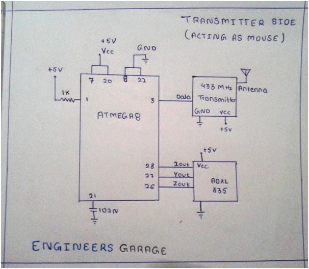 |
Project Video
Filed Under: Electronic Projects
Filed Under: Electronic Projects

Questions related to this article?
👉Ask and discuss on Electro-Tech-Online.com and EDAboard.com forums.
Tell Us What You Think!!
You must be logged in to post a comment.