This is the most advance version of “Pick and Place Robot” perhaps and most popular and widely used in recent industries. A person from a remote place can comfortably control the motion of robotic arm without any wire connection.
Again there are two systems one at the transmitter side in which a software program written in VC++ generates control signals. These signals are encoded and transmitted by RF transmitter chip. At another end RF receiver chip will demodulate these signals and decoder will decode it. Finally 89C51 will take desired controlling action on robotic arm.
This one is similar kind of project as pick n place robot but there are two major changes
1) The mechanical structure is wirelessly controlled from a remote computer
2) The mechanical structure a robotic arm is actually working instrument in industries not just simple project
Here a man from a remote place of around 50-100 mts range sitting on his chair with his computer can easily control the mechanism by the keyboard or mouse. An ASK transmitter attached with computer transmits the controlling codes. These codes are received by ASK receiver, decoded and given to 89C51 which then controls the motion of robotic arm. So as per user command through computer the motion of robotic arm is controlled from a remote place without any wire connection.
Let us first start with mechanism
Mechanical structure of Robotic Arm:-
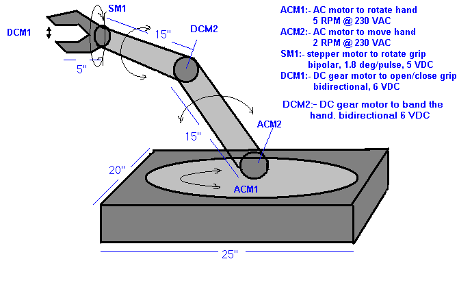
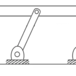
The figure given below shows complete outer structure of robotic arm. The complete body is made up of solid steel. All the motions are perfectly calibrated and controlled. The complete size with all dimensions are as indicated. There are various motions in this arm
- Circular motion of hand: – the arm can rotate complete in 360o circle with the help of ¼ HP, 0.2 A, 230 V bidirectional AC motor (ACM1) which has maximum of 5 RPM at rated 230 VAC
- Vertical motion of hand: –the hand can move down lower then 0o up to -30o to maximum up to 90o. This motion is divided in two parts. Lower hand and upper hand. The lower hand moves up and down due to ¼ HP, 0.2 A, 230 V bidirectional AC motor (ACM2) which has maximum of 5 RPM at rated 230 VAC. The upper hand is moved by 6 V DCgear motor (DCM2)
- Circular motion of grip: – the grip can freely rotate in either direction in complete 360o circle due to 5 VDC bipolar stepper motor with 18o step resolution.
- Opening closing of grip:-the maximum opening of grip is 5 cm and minimum is 0.5 cm. the same type of 6 VDC gear motor (DCM1) is utilize for this motion.
So for all the motions we have one motor total of five motors. All five motors provides full flexibility to mechanism so that it can pick and place an object vary easily.
Now we shall start with controlling of this mechanism. There are two parts
1) Computerize ASK transmitter: – this is a small hardware attached to LPT port of computer which transmits the action codes given by a software program prepared in VC++.
2) 89C51 based ASK receiver: – it consist of ASK receiver, decoder and micro controller 89C51. It controls all the motions of robotic arm by controlling all five motors depending upon the command given by user.
Computerized ASK Transmitter
Computerize ASK transmitter: –
This part is further divided in to two parts (1) software and (2) hardware
Software Part: – the figure given below shows application design.
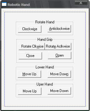
It has 10 command buttons for 10 different motions. Here is the description for their properties.
|
Sr. No. |
item |
property |
setting |
function |
|
1 |
Button1 |
ID caption |
IDC_CLK Clockwi&se |
Rotates hand 30o clockwise when button is pressed once |
|
2 |
Button2 |
ID caption |
IDC_ACLK &AntiClockwise |
Rotates hand 30oanticlockwise when button is pressed once |
|
3 |
Button3 |
ID caption |
IDC_CLKW Rotate Clock&wise |
Pressing the buttons once will rotate the grip 75oclockwise |
|
4 |
Button4 |
ID caption |
IDC_ACLKW Rotate Anticlockwis&e |
Pressing the buttons once will rotate the grip 75oanticlockwise |
|
5 |
Button5 |
ID caption |
IDC_CLS C&lose |
Opens the grip by 0.5 cm on pressing button once |
|
6 |
Button6 |
ID caption |
IDC_OPN &Open |
Closes the grip by 0.5 cm on pressing button once |
|
7 |
Button7 |
ID caption |
IDC_UP1 &Move Up |
Moves lower part of hand 30o upward when button is pressed once |
|
8 |
Button8 |
ID caption |
IDC_DWN1 Move Dow&n |
Moves lower part of hand 30odownward when button is pressed once |
|
9 |
Button9 |
ID caption |
IDC_UP2 Move Up |
Moves upper part of hand 30o upward when button is pressed once |
|
10 |
Button10 |
ID caption |
IDC_DWN2 Move Down |
Moves upper part of hand 30odownward when button is pressed once |
Actually each button sends one particular code to LPT port that will be transmitted by ASK transmitter. Each code triggers on particular motion in hand.
One of the functions that send code to LPT is as written below
void CRoboticHandDlg::OnClk()
{
// TODO: Add your control notification handler code here
_outp(0x0378, 0xE1); //enables transmission and sends the code to LPT
Sleep(200); // wait for 0.2 second
_outp(0x0378,0x10); // disable transmission
}
Here are the codes that triggers one particular motion
01h* : rotate hand clockwise
02h : rotate hand anticlockwise
03h : rotate grip clockwise
04h : rotate grip anticlockwise
05h : move lower hand upward
06h : move lower hand downward
07h : move upper hand upward
08h : move upper hand downward
* “h” indicates all the codes are in hex format.
Now let us see the small hardware that will transmit these codes
Hardware Part: –the block diagram of this part is as shown in figure.
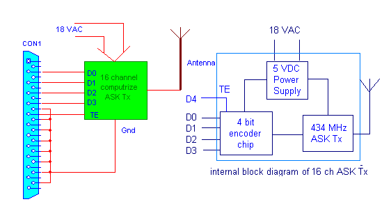
As shown in figure a 16 channel ASK transmitter is connected with 25 pin D-type male/female connector. The data pins D0-D3 of connector are connected with data pins of encoder chip (HT12E). The D4 pin connected with transmission enable (TE) pin of encoder chip. The output of encoder chip is given as input to 434 MHz ASK transmitter that will modulate the data with carrier signal and transmit it via suitable antenna. As there are four bits we can send maximum 16 different codes through this transmitter that’s why it is 16 channel ASK transmitter.
89C51 Based ASK Receiver
89C51 based ASK receiver: –
The figure given below shows the circuit diagram of receiver
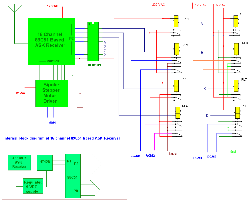
The main blocks of receiver are 89C51 based ASK receiver, current driver chip ULN and bipolar stepper motor driver.
ULN chip is used to energize 8 relays which turn ON or OFF all four motors (2 AC and 2 DC motors) and also change its direction. There are 8 relays out of them 4 are single change over (c/o) and other 4 are two change over. To start or stop the motor and also change its direction one single c/o and one two c/o relay are needed. The connection is done such a way that when single c/o relay is energized it will start the motor and when de-energized stops the motor. Second 2 c/o relay changes the direction as it changes over from one to other position. Thus each motor needs two relays one for start and stop and second for direction change.
The standard H-bridge circuit is used in bipolar stepper motor driver. For more details of this circuit click here.
Internal blocks of receiver are also indicated in corner. The main parts are 434 MHz ASK receiver, decoder chip (HT12D) and micro-controller 89C51. The ASK receiver will demodulate the signal and give encoded data to decoder. Decoder will decode it and gives to 89C51. The port P0 of 89C51 is used to control stepper motor through driver and port P2 is used to control other four motor through ULN chip. All eight pins of P2 drives one relay thorough ULN chip.
The heart of whole circuit is 89C51 as it handles all the functions like getting code from decoder, compare them with stored codes, control the motion of hand by triggering any of the five motors. It performs eight different functions as told by transmitter on getting eight different codes. It has eight subroutines for these functions. Each code when received and decoded will call one particular subroutine. When subroutine is executed the program again waits for next user command. At a time we can send only one command so only one motion is triggered at a time.
Working operation: –
- On pressing any of command buttons from computer program will send one of the codes to LPT port. For example code 02h is sent to rotate hand anticlockwise
- The ASK transmitter attached to LPT will transmit the code over 434 MHz carrier
- On receiver side ASK receiver demodulate the code and give to decoder chip
- The decoded code is given to 89C51. It will compare this code with stored codes and when match found it will energize RL1 and RL2 both to rotate ACM1 anticlockwise so that hand will rotate anticlockwise. The controller will exactly move hand to 30o and then stops it.
- Now controller will wait for next command
- Again when next command button is pressed same process repeats
You may also like:


Filed Under: Electronic Projects

Questions related to this article?
👉Ask and discuss on Electro-Tech-Online.com and EDAboard.com forums.
Tell Us What You Think!!
You must be logged in to post a comment.