SIM800 is a popular GSM GPRS modem. It supports General Packet Radio Service (GPRS) for connecting to the Internet. This module has built-in TCP/IP stack that can be accessed serially with AT commands. The modem needs to be configured by connecting it to a PC. In such setup, the SIM800 modem with SIM card acts as TCP client and the PC acts as TCP server.
The client first connects to the server and sends some data to server and the server also responses with some data in order to acknowledge for receiving the data. This modem does not have any kind of processor with itself, so it requires a microcontroller like Arduino to drive it. In the configuration setup for the modem, the Arduino board acts as USB to Serial converter.
Component Required –
1) Arduino UNO R3 board or any compatible board
2) SIM800 GSM module
3) Connecting wires
4) Micro SIM card (from any telecom operator)
Circuit Connections –
SIM800 modem supports AT commands over serial communication. For connecting it with the computer, it must be interfaced with a controller as it does have any controller on itself. The Arduino UNO is used in this configuration setup. The Arduino UNO acts as USB-to-serial converter. It acts as a gateway between the computer and the modem to provide serial communication to the modem. The configuration setup has the following circuit connections –
SIM800 – SIM800 is the GSM GPRS modem used in this configuration setup. The same is configured to connect with GPRS network with the help of a PC as TCP-IP server. The modem has the following pin configuration –
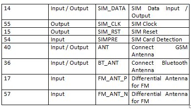
Fig. 1: Table Listing Pin Configuration of SIM800 Module

Fig. 2: Table Listing Pin Configuration of SIM800 Module

Fig. 3: Table Listing Pin Configuration of SIM800 Module

Fig. 4: Table Listing Pin Configuration of SIM800 Module
On a module, only some of the pins mentioned above may be available. Generally pins for audio interfacing, GPIO pins, power supply and serial communication are left available in the modules purchased from the market.
Power Supply – It should be taken care that SIM800 module uses operating input voltage of 3.7V-4.2V. Therefore it should not be provided 5V of Arduino otherwise that might damage the module as well. The modem could have provided 3.3V of Arduino but this can also heat the modem as modem will not get enough power to operate. So, it is strongly suggested that an external power source should be used to get the desired voltage with sufficient current. A battery is a good option to use as external source otherwise a constant power source like LM317 would be great to use. It must be made sure that the power source provides enough current to the modem to operate.
As the modem has 5V tolerant input levels, there is no need of logic level converter but some of the modems works on the principle of CMOS logic so there will be need of logic level converter because Arduino works on TTL logic level. The module should be connected with the power supply as follow –

Fig. 5: Table Listing Power Supply Connections to SIM800 Module
A proper power source must be selected according to the GSM GPRS Modem in use. The SIM800 modem used in this configuration setup works best with 3.7 V power supply. When the SIM800 modem is powered ON, there is a network status LED which must turn ON in the GSM modem. In starting, LED blinks every 1 second which means SIM is not connected to the network and is searching for the network. If it gets connected to the network, it blinks every 3 seconds.
Arduino UNO – The Arduino is used as USB to Serial Adaptor. The SIM_TX pin of GPRS modem is connected to the TX of Arduino and the SIM_RX pin of GPRS modem is connected to RX of Arduino. The GND pin of the GSM modem can be connected to any GND of Arduino. The circuit connections between Arduino UNO and SIM800 Module are summarized in the following table.

Fig. 6: Table Listing Circuit Connections between Arduino and SIM800 Module
The Arduino must be programmed to work as USB to Serial adaptor. An open-source Arduino Sketch for that can be downloaded from internet. The Arduino should be connected with the PC using a USB cable.
Setting up PC as a TCP-IP server
For making PC as a server, the socket test application is used. Socket test application has the capability to act as client as well as server. The socket test application shows the IP address of the connected clients The client in this case is the SIM800 modem.
For Configuration of socket test application to act as PC server, follow the below steps –
1) First open up the socket test application and under the server tab, write the private IP address of the PC on which the application is running. 2) Write the random selected port on which the PC is listening. As seen below, the server is listening on port “123”.
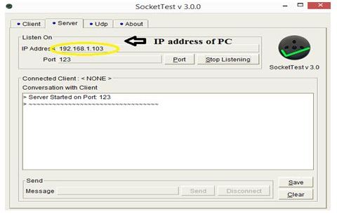
Fig. 7: Screenshot of Server Tab in SocketTest Application
If the server is still not listening on port “123”, it can be checked by online at “canyouseeme.org” where it can be checked if the server is not listening on port “123”.
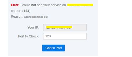
Fig. 8: Screenshot of Checking Server Port at CanYouSeeMe.org
There may need to open a port in windows firewall as firewall prevents unauthorized access to computer resources. In order to let the specific IP communicate with the computer, go to control panel -> Windows Firewall -> Advanced setting. A new window will be opened named Windows firewall with advanced security. In that window, go to Inbound Rules -> New rule ->PORT -> TCP and write port no. in specific local ports block and then, go to Allow the connection -> next -> preferred name and Finish.
3) Next, do port forwarding so that the ISP will not block the particular port. For port forwarding, type the default gateway IP address which is usually 192.168.1.1 in the browser then go to Advanced Setup -> NAT -> Add PC server with the local IP of PC and port with the 123. Then, open canyouseeme.org and check with the port used. The window must show a message as shown bellow –
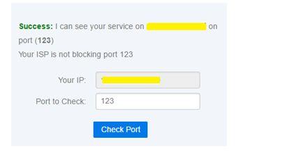
Fig. 9: Screenshot of Verifying Server Port at CanYouSeeMe.org
In this way, the port is registered with the PC server and now it can be used to access the server via the client.
For serial communication, Tera Term VT tool is used. Download this terminal application from the following link –
Configuring SIM800 using PC as TCP-IP Server
After making circuit connections and setting PC as server, insert a valid SIM card to the card slot of the modem and wait until it is not connected to the network. Be sure not to touch the SIM800 IC chip. Next open the Tera Term VT application on PC and follow the below steps –
1) First, send the AT command on serial monitor to see if the modem is working properly or not. The modem should respond with OK. The following command should be written on the terminal window for this –
AT
2) Then send AT+CREG? command to see SIM is registered on network or not. If the SIM is registered to network then it should response with +CREG: 0,1 or +CREG:1,1. This command is necessary to check because all the further process depends on the network connection. The following command should be written on the terminal window for this –
AT+CREG?
3) Now when the SIM is connected to the network, attach the device to the packet domain service. The device is attached to the GPRS network before a PDP context can be established. It should response with OK, when it connects to the GPRS network. The following command should be written on the terminal window for this –
AT+CGATT=1
4) Next, if everything is working fine, check if the modem has any previous TCP connections. If the SIM has any TCP connections then close all the previous connections because a new connection must be started. The modem should respond with SHUT OK. The following command should be written on the terminal window for this –
AT+CIPSHUT
5) Next, set the IP connection as single IP (AT+CIPMUX =n, i.e. n=0) or multiple IP connection (i.e. n=1). The single IP connection is created here. The device should respond with OK when it establishes a single IP connection. The following command should be written on the terminal window for this –
AT+CIPMUX=0
6) Set up the APN for TCP connection. The APN, username and password for the SIM card must be known. An Airtel SIM is used here and any username and password has not been set to access the SIM. It should response with OK. The following command should be written on the terminal window for this –
AT+CSTT= “airtelgprs.com”, “”, “”
7) Now bring up the wireless connection with the Internet. This command takes some time to respond OK. Now the device is connected to the TCP/IP wireless connection. Now, it can be seen that in the modem, the Network status LED starts blinking speedily (3 blinks/sec). The following command should be written on the terminal window for this –
AT+CIICR
8) Use AT+CIFSR command to return the local IP address of the device. Now, the SIM800 modem IP address can be seen when connected to the communication network. The response should be 192.168.1.XXX. The following command should be written on the terminal window for this –
AT+CIFSR
9) As the client and server communication is provided over TCP protocol, there must start a TCP/IP connection on the client side. This can be enabled by using the command AT+CIPSTART= “TCP”, “server domain name (Public IP)”, “PORT”. Write the server domain name from which is to communicate and the port on which server is listening. In this case, server is listening on “123” port. It should response with CONNECT OK. The following command should be written on the terminal window for this –
AT+CIPSTART= “TCP”, “server domain name (Public IP)”, “PORT”
10) Finally the TCP/IP connection is established on the client side and TCP/IP connection on the server side has been already established. Now send some data to the server. Through this command, some data is sent to the server on the specified port. It should response with > (right shift arrow). Now type the message to be sent like “Hello PC server” and press CTRL+Z from the keyboard to send the message , it should respond with SEND OK. The following command should be written on the terminal window for this –
AT+CIPSEND
On the server side, the message from the particular client should be received. The server can also send some message to the client in order to provide two-way communication between client and server. In this way, the client and server communicates with each other over TCP/IP protocol.
There can be some possible errors which should be handled as mentioned below –
• If modem is not able to communicate serially with computer then check whether baud rate is set to 9600 or not because modem needs 9600 baud rate to communicate with computer.
• If the modem is not able to connect with the network then check for the power supply. It should be checked if the module is getting enough current or not i.e. 2A. If the module is getting enough current then error may be because of the SIM card. Try to change the SIM card, choose the SIM card with high level sensitivity in the location.
• Before applying AT+CSTT command to APN, username and password, check if modem is attached to GPRS or not by using AT+CGATT? command. If the result is +CGATT:0 this modem is not attached to GPRS, so attach the modem using AT+CGATT=1 command.
• If the internet connection is working which can be checked by opening a website on the browser but not getting connected with PC server, the possible reason for the TCP connection close error may be because of the port might not have been registered on windows firewall of the PC. Follow the above mentioned instructions to enable the port on windows firewall and port forwarding.
In the next tutorial, learn to implement MQTT protocol over SIM800 Modem.
You may also like:
Filed Under: IoT tutorials, Tutorials




Questions related to this article?
👉Ask and discuss on EDAboard.com and Electro-Tech-Online.com forums.
Tell Us What You Think!!
You must be logged in to post a comment.