You may have seen many micro controller based GPS receivers. The main purpose of such GPS receivers is to locate and display device latitude and longitudes (co-ordinates). These GPS receivers are built using micro controller and LCD screen. Most of the receivers display location co-ordinates only. Some may display time and date along with co-ordinates. But only few GPS receives display full information like time, date, location, height, speed, direction, number of satellite in view, validity and accuracy of signal etc. so many details.
Here the given GPS receiver also displays
· Time – Indian standard time
· Date – current date
· Co-ordinates – latitude longitude
· Speed of an object in km/hr
· Moving direction – course angle
· Height (altitude) of an object from sea level
So, all most all the required details regarding device or an object is displayed on LCD screen. The project is built using Arduino nano development board and it uses 16×4 alphanumeric LCD panel to display above information.
Circuit description:
· GPS receiver has 3 wire interface with arduino Tx, Rx and Ground. Its Tx pin is connected with RXD pin of arduino. Rx pin is left unconnected (because we don’t need it here). Ground pin is connected to board ground. Also the GPS receiver is given Vcc supply through arduino board
· LCD data pins D4 – D7 (11 – 14) are connected with arduino digital pins 10 – 13. Its control pins Rs (4) and En (6) are connected with arduino digital pins 8 and 9 respectively.
· Two more Control pins RW (5) and VEE (3) of LCD are connected to ground
· Back light LED pins 15 and 16 of LCD are connected to Vcc and Gnd of board to turn ON back light
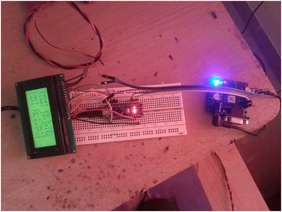
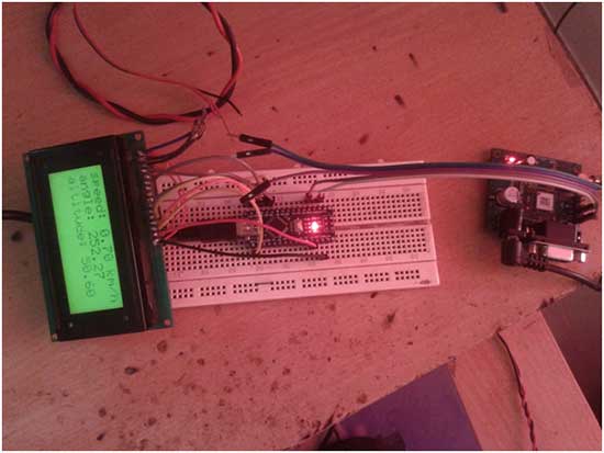
Snaps of circuit arrangement
Circuit operation:
· Initially the circuit is given power from arduino board through USB. The message is displayed on LCD as “Arduino GPS receiver”
· Then arduino waits for few seconds and tries to get serial data from GPS receiver. The GPS receiver requires few seconds to get initialized and to get connected with satellites. At this time the message is displayed on LCD as “Initializing…..”
· When GPS receiver gets connected with satellite, it calculates the co-ordinates and gets the other information like time, date, speed, altitude etc
· Then it encodes this information into serial format using NEMA protocol* and start sending several serial strings to arduino. All the strings are starting from ‘$’ sign. There are several strings like $GPGGA, $GPRMC, $GPGSV, $GPGSA etc sent to arduino
· Arduino receives all these strings from GPS receiver and decodes them using TinyGPS library. Using this library, arduino extracts latitude, longitude, time, date, antenna angel, speed, and height (altitude) etc all information from these strings.
· Then arduino displays time#, date, latitude and longitude on LCD screen for 5 second and after 5 second it displays speed, height and angle for 5 second
· Thus after every 10 second the display is updated with new data
*Note 1: all most all GPS receivers works on standard NEMA protocol. It forms several serial strings starting with $ sign and operates on 4800 bps or 9600 bps.
*Note 2: the time from GPS is UTC – Greenwich mean time. It is converted into IST (Indian standard time) by adding +5:30.
Project Source Code
###
//The program is downloaded into internal flash of arduino NANO micro controller ATMega328A. The program is edited and compiled using arduino IDE software. It uses TinyGPS library to decode GPS strings and get the required information. It also uses LCD library to display this information on LCD screen #include#include TinyGPS gps; //Creates a new instance of the TinyGPS object LiquidCrystal mylcd(8,9,10,11,12,13); float lat, lon,course_angle, speed_kmph,alti; unsigned long age,fix_age; int yr; byte mnth,dy,hr,mn,s,hund; void setup() { Serial.begin(9600); mylcd.begin(16,4); mylcd.clear(); mylcd.print(" GPS Receiver"); delay(3000); mylcd.clear(); mylcd.print("initializing...."); delay(3000); } void loop() { while (Serial.available()) { if (gps.encode(Serial.read())) { gps.f_get_position(&lat, &lon, &age); gps.crack_datetime(&yr, &mnth, &dy, &hr, &mn, &s, &hund, &fix_age); course_angle = gps.f_course(); speed_kmph = gps.f_speed_kmph(); alti = gps.f_altitude(); mn+=30; if(mn>60) { mn-=60; hr++; } hr+=5; mylcd.clear(); mylcd.print("Date: "); mylcd.print(dy); mylcd.print('/'); mylcd.print(mnth); mylcd.print('/'); mylcd.print(yr); mylcd.setCursor(0,1); mylcd.print("Time: "); mylcd.print(hr); mylcd.print(':'); mylcd.print(mn); mylcd.print(':'); mylcd.print(s); mylcd.setCursor(0,2); mylcd.print("Lat: "); mylcd.print(lat== TinyGPS::GPS_INVALID_F_ANGLE ? 0.0 : lat, 6); mylcd.setCursor(0,3); mylcd.print("Lon: "); mylcd.print(lon == TinyGPS::GPS_INVALID_F_ANGLE ? 0.0 : lon, 6); delay(5000); mylcd.clear(); mylcd.print("speed: "); mylcd.print(speed_kmph); mylcd.print(" km/h"); mylcd.setCursor(0,1); mylcd.print("angle: "); mylcd.print(course_angle); mylcd.setCursor(0,2); mylcd.print("altitude: "); mylcd.print(alti); delay(5000); } } } /*End of Program*/ ###
Circuit Diagrams

Project Video
Filed Under: Electronic Projects
Filed Under: Electronic Projects

Questions related to this article?
👉Ask and discuss on Electro-Tech-Online.com and EDAboard.com forums.
Tell Us What You Think!!
You must be logged in to post a comment.