In this project, a device will be designed which will allow controlling a servo motor from the desktop computer on USB interface. For controlling a servo motor, PWM output needs to be generated from the microcontroller. The length of the ON time of the PWM signal at the control pin of the servo determines the angle the servo should rotate. The project device receives data from the host computer on USB interface which will determine the ON time of the PWM signal and according a PWM signal will be sent out to the control pin of the servo using in-built timer.
For this, the device will be configured as HID Class Device again. An HID Class device has USB communication over two types of transfers – Control transfer and Interrupt transfer. The control transfer will be used for enumeration of the device. After enumeration, data packets will be read from the computer for determining rotation angle. The Tower Pro SG-90 servo motor is used in the project which can rotate about 180 degrees. The rotation angle is denoted from negative 90 degree to positive 90 degree.

Fig. 1: Prototype of Arduino based USB Servo Motor Controller
The project will need a controller chip to handle USB data from the computer and to operate servo motor accordingly. The 8-bit USB AVR – Atmega 32u4 is used as the device controller chip in the project. The project uses AVR based Lightweight USB Framework (LUFA) as the firmware which will be responsible for implementation of the USB Protocol. The device is tested on a Linux system using Python based Pyusb and Libusb frameworks for sending data to the peripheral device from the host computer.
The Generic HID device driver class of the LUFA firmware is used and modified to program the project. With the use of LUFA firmware, the device driver code to implement USB protocol is not needed to be written explicitly. Modifying the firmware code will be sufficient to implement the USB protocol.
PREREQUISTES
This project is based on Arduino Pro Micro which has the USB AVR – Atmega 32u4 as the sitting MCU. In order to understand this project, one must have basic knowledge of the AVR microcontrollers and the embedded C programming for AVRs. WinAVR Studio is used to write, edit and compile the project code, so closely following the project shall require familiarizing with the above stated IDE as well. Though LUFA framework takes care of implementing the USB protocol and has APIs to abstract the lower level codes, understanding USB protocol is recommended to understand how actually the project is working. In fact, if anyone has already worked on some other microcontroller, it will not be much pain to understand and follow this project as the project code is more or less about modifying the LUFA device driver to work as generic HID device and generating PWM output from the Arduino board. One must have additional knowledge of Linux operating system (Ubuntu) and should be knowing basic Linux commands. One having knowledge of Python programming language is recommended but not mandatory for implementing the project.
COMPONENTS REQUIRED
1. Arduino Pro Micro
2. Connecting wires
3. Tower Pro SG-90 servo motor
4. Micro USB cable
SOFTWARE TOOLS REQUIRED
1. WinAVR Studio
2. AVR Dude
5. Pyserial 2.7
BLOCK DIAGRAM

Fig. 2: Block Diagram of Arduino based DIY USB Servo Motor Controller
CIRCUIT CONNECTIONS
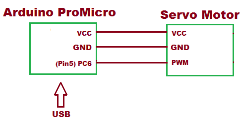
The project uses Arduino Pro Micro as the USB controller chip and uses Tower Pro SG-90 servo motor. The servo motor has three wires – VCC, Ground and Control. The VCC and Ground wires are connected to the common VCC and ground respectively. The Control wire of the servo is connected to the pin 6 of Port C which is pin 5 on the Arduino Pro Micro. Therefore, the Arduino and servo motor will have connections according to the following table -:

Fig. 3: Table listing circuit connections between Arduino Pro Micro and Servo Motor
The Program code for the project is burnt to the Arduino Pro Micro using AVR Dude. The Arduino board is connected to the USB port of a PC by a USB cable.
HOW THE PROJECT WORKS
In this project the USB protocol is implemented by the LUFA framework. For configuring the controller chip to work as Generic HID device, the HID Class Driver of the LUFA framework will be used. The Human Interface Device (HID) class takes care of the transfers between the host device and the human controlled USB peripherals like USB Keyboard, Mouse or Joystick.
When a USB device is attached to the host (PC), the host sends request for configuration details in the form of control transfer. The connected device has to respond with appropriate descriptors to get configured and ready for further operations. Only after configuration, the device can communicate with the host in the form of interrupt, isochronous or bulk transfers for executing the operations for which the device has been made. This process of identification and configuration of the device with the host is called enumeration. . The device designed in this project uses control transfer to enumerate with the host computer and send data to the microcontroller. The data will be exchanged using Class-Specific Requests. These Requests are sent by Host to Device via Control Transfer. The Set_Report is the request by which Host can send data to the device. Check out the Atmega 32u4 Based LED Series Project for learning about the Set_Report Class specific request.
Fig. 4: Prototype of Arduino based USB Servo Motor Controller
The project is based HID class driver of USB and LUFA framework has HID class related module in the LUFA-Source-Folder /LUFA/Drivers/USB/Class/Device folder. Other device class related module are also in the same folder. The LUFA framework has demo projects for different USB device classes in the LUFA-Source-FolderDemosDeviceClassDriver folder. For implementing the project, demo project for Generic HID devices provided in the LUFA framework will be modified and complied. The demo project for Generic HID devices is in the LUFA-Source-FolderDemosDeviceClassDriverGenericHID folder. The folder contains GenericHID.c file which will be modified to implement the project.
How GenericHID.c identifies HID device being Generic HID device
The GenericHID.c uses Generic_HID_Interface interface in HID_Device_USBTask() function which is being imported from the HIDDeviceClass.c (from LUFA-Source-Folder LUFADriversUSBClassDevice) to configure the device as generic HID device. The interface abstracts the low-level descriptor codes and identifies the device as generic HID device through an InterfaceNumber variable.
Generic HID Device Specific Report Descriptors
Any HID device has to exchange data with the host which should be structured in the form of reports. The report descriptor defines the report structure. A report descriptor contains the information needed by host to determine the data format and how the data should be processed by the host. Therefore, a report descriptor basically structure the data that needs to be exchanged with the host according to the USB protocol.
For working like a generic USB HID device, the device needs to send usage report and data input report descriptors specific to Generic HID Class to the host while it itself needs to interpret data output report specific to Generic HID Class received from the host device. The Usage Report informs the Host about the features or functionality of the USB device. The Data Output Report is used to receive data from the host while Data Input report is used to send data to the host.
From Where GenericHID.C gets the USAGE and Data Reports Descriptors
In the LUFA framework’s demo project for GenericHID, GenericHID.h is imported. The GenericHID.h imports descriptor.c file which defines the relevant usage and data reports descriptors for the host device. The descriptor.c defines a GenericReport[] structure to generate generic HID usage and data reports descriptors. Inside descriptor.c the GenericReport[] structure has the values returned by HID_DESCRIPTOR_VENDOR () function. The HID_DESCRIPTOR_VENDOR () is defined in HIDClassCommon.h (located in LUFA-Source-FolderLUFADriversUSBClassCommon folder).
The GenericHID.c imports GenericHID.h which imports usb.h. USB.h imports HIDCLass.h. In HIDClass.h is imported HIDClassDevice.h if the USB_CAN_BE_DEVICE is true for the controller chip to being a USB device not the host. The HIDClassDevice.h imports HIDClassCommon.h where the HID device specific descriptor fields have been defined.
USAGE REPORT
HID_DESCRIPTOR_VENDOR () returns the field values of the usage report descriptor, specific to generic HID device functioning. The fields are set to following values in HID_DESCRIPTOR_VENDOR ().

Fig. 5: Screenshot of HID_DESCRIPTOR_VENDOR Function in LUFA
The Usage or Feature report contains information about the features of the device. In other words, this report informs Host about the features needed in the device. A generic HID device is a vender defined device and can simply send or data on the USB interface.
DATA INPUT AND OUTPUT REPORT
The Data Input and Output report for generic HID device simply contains data of a size restricted by the usage report. It is defined in the following manner -:

Fig. 6: Screenshot of Data Input and Output report for generic HID device in LUFA
In LUFA framework, both the data input and data output reports are restricted to contain data packet 8-byte long. In this project, only two bytes of the data packet will be utilized.
HOW THE DEVICE WORKS
The Servo motor operates on PWM technique with a fix time period. The SG – 90 operates on a PWM signal having a total time period of 20 ms with ON time varying from 1ms to 2ms. The ON time of PWM signal decides the angular movement of the motor. The ON time of 1 ms makes angular movement of -90 degrees whereas 1.5 ms makes angular movement of 0 degrees (middle position) and 2 ms make angular movement of 90 degrees. The in between values of ON time can be used for angular movement from -90 degrees to 90 degrees.
The inbuilt timer 3 will be used to generate a PWM signal of time period 20 ms to control servo motor. The timer will be used in Fast PWM mode. The Input Compare Register of Timer3 will be used to create a 20ms time period. The Output Compare Register of Timer3 will decide the ON time of the PWM signal.
Fig. 7: Prototype of Arduino based USB Servo Motor Controller
The device will receive data from the host computer on control transfer. The data report contains the angular movement data provided by the Host PC to the device. Since, data is to be received from the host device CALLBACK_HID_Device_ProcessHIDReport() function of the GenericHID.c will be modified. The main() function of the GenericHID.c will also be modified to make the microcontroller aware of the circuit configuration and initialize timers. On PC side, a Python Application will be used to send data report for controlling the servo motor. The Application will be based on Python programming language and will run on Linux distribution like Ubuntu. It will use Pyusb and Libusb framework for sending data on the USB protocol. The Application will issue a Set_Report request to transfer the data to Device (microcontroller).
The Host will send the Angular Movement and Axis or Side details to Device using Data Report message. The parameters of 2 byte Data Report are -:

Fig. 8: Table listing Data Report Messages
The Byte0 will tell our hardware device about the positive or negative axis or side movement. For example, for negative side movements, it will send 0x01 else 0x00. Byte1 will indicate the angle between 0 and 90 that needs to be made by servo motor.
Check out the program code to see the modifications implemented for the project.
PROGRAMMING GUIDE
For building the project download the LUFA framework from the github.com. The demo project provided with the LUFA framework is modified to make the project. In the extracted LUFA zip file, open Demos/Device/ClassDriver/GenericHID folder. The folder has the following files and folders.

Fig. 9: Screenshot of LUFA library on Windows
Of these, GenericHID.h, GenericHID.c and Makefile needs to be modified for this project.The modified files (provided at the bottom of the article in zip format) can also be downloaded from the engineersgarage and replaced with the original files. Either open the files in WinAVR Studio or Notepad++ and modify original files or replace files with the already modified one. The modified or replaced GenericHID.c needs to be compiled from within the LUFA’s Source folder to get the object code.
A python script has been written to run on the desktop side. The script can be written and saved as a file during testing this USB device or it can be downloaded along with the other project files from engineersgarage and run using command prompt or a command line interpreter during testing of the device.
Modifying GenericHID.h
The GenericHID.h library file is imported in the GenericHID.c file and includes a set of additional libraries and defines the constants and functions for the Generic HID device. These include the additional libraries for the LED board which should be commented out as the project is not using that HID feature. So open GenericHID.h and make the following changes -:
• Comment the #define statements for LEDMASK_USB_NOTREADY, LEDMASK_USB_ENUMERATING, LEDMASK_USB_READY, LEDMASK_USB_ERROR
Save the file with changes.
Modifying GenericHID.C file
Again in the GenericHID.c, the code sections for LED board needs to be commented out. So open GenericHID.c and make the following changes -:
• In the main loop, comment the LEDs_SetAllLEDs()
• In SetupHardware() function, comment the LEDs_Init()
• In EVENT_USB_Device_Connect() function, comment the LEDs_SetAllLEDs()
• In EVENT_USB_Device_Disconnect() function, comment LEDs_SetAllLEDs()
• In EVENT_USB_Device_ConfigurationChanged() function, comment the LEDs_SetAllLEDs()
In the main function, we need to declare PC6 as output pin. The PC6 (OC3A) is the pin at which PWM output can be obtained. The Timer 3 also needs to be initialized for Fast PWM mode. So add the following statements in the main() function -:
Inside the infinite for loop the HID_Device_USBTask() function is called where Generic_HID_Interface interface is passed as parameter. The interface identifies the device as Generic HID device and abstracts the low level program code specific to Generic HID class. The function is coming from the HIDClassDevice.c module (located in LUFA/Drivers/USB/Class/Device/HIDClassDevice.c) and is used for general management task for a given HID class interface, required for the correct operation of the interface. It should be called in the main program loop, before the master USB management task USB_USBTask(). The USB_USBTask() is the main USB management task. The USB driver requires this task to be executed continuously when the USB system is active (device attached in host mode, or attached to a host in device mode) in order to manage USB communications. The function is defined in USBTask.c (Located in LUFA-Source-FolderLUFADriversUSBCore folder).
For creating the Data Output report CALLBACK_HID_Device_ProcessHIDReport() function needs to be modified. The default file has the function body to transmit data to an LED board.

Fig. 10: Screenshot of CALLBACK_HID_Device_ProcessHIDReport Function in LUFA
The controller chip receives 2-byte data from the host computer and according to that data, it changes generates PWM output to the servo motor. So replace the body of the function with the following code -:
The Data Input Report (to send data from device to the host) is handled by the CALLBACK_HID_Device_CreateHIDReport() function. In the unedited LUFA file, this function has statements to report back the status of LED board and has the following body -:

Fig. 11: Screenshot of CALLBACK_HID_Device_CreateHIDReport Function in LUFA
All the statements in this function will be removed as the device will not send any data to the host computer. Therefore, the CALLBACK_HID_Device_CreateHIDReport() function will be left with an empty body -:
Save the file and create Make file for the project.
Modifying Make File
In the GenericHID folder there is a make file that needs to be edited. The file can be edited using Notepad++. The following information needs to be edited.
• MCU = atmega32u4
• ARCH = AVR8
• BOARD = LEONARDO
• F_CPU = 16000000
Save the file and exit. Now all the files are edited completely for the Servo Control Project.
Compiling GenericHID.c
For compiling the source code, WinAVR Programmers Notepad or Arduino IDE can be used. Open the modified GenericHID.c file and compile the code.
BURNING HEX CODE
The hex file is generated on compiling the GenericHID.c file. For burning the object code to microcontroller open the Command Prompt, change the current directory to the directory containing the Hex file. This can be done using command: CD <address of the directory>. Now reset the Arduino and instantly run the command: avrdude -v -p atmega32u4 -c avr109 -P COM20 -b 57600 -D -Uflash:w:GenericHID.hex:i after replacing the COM Port with the recognized one. If using Linux, the COM port name will be like /dev/ttyACM0.
TESTING THE DEVICE
Project Source Code
###
/* LUFA Library Copyright (C) Dean Camera, 2015. dean [at] fourwalledcubicle [dot] com www.lufa-lib.org */ /* Copyright 2015 Dean Camera (dean [at] fourwalledcubicle [dot] com) Permission to use, copy, modify, distribute, and sell this software and its documentation for any purpose is hereby granted without fee, provided that the above copyright notice appear in all copies and that both that the copyright notice and this permission notice and warranty disclaimer appear in supporting documentation, and that the name of the author not be used in advertising or publicity pertaining to distribution of the software without specific, written prior permission. The author disclaims all warranties with regard to this software, including all implied warranties of merchantability and fitness. In no event shall the author be liable for any special, indirect or consequential damages or any damages whatsoever resulting from loss of use, data or profits, whether in an action of contract, negligence or other tortious action, arising out of or in connection with the use or performance of this software. */ /** file * * Main source file for the GenericHID demo. This file contains the main tasks of * the demo and is responsible for the initial application hardware configuration. */ #include "GenericHID.h" /** Buffer to hold the previously generated HID report, for comparison purposes inside the HID class driver. */ static uint8_t PrevHIDReportBuffer[GENERIC_REPORT_SIZE]; /** LUFA HID Class driver interface configuration and state information. This structure is * passed to all HID Class driver functions, so that multiple instances of the same class * within a device can be differentiated from one another. */ USB_ClassInfo_HID_Device_t Generic_HID_Interface = { .Config = { .InterfaceNumber = INTERFACE_ID_GenericHID, .ReportINEndpoint = { .Address = GENERIC_IN_EPADDR, .Size = GENERIC_EPSIZE, .Banks = 1, }, .PrevReportINBuffer = PrevHIDReportBuffer, .PrevReportINBufferSize = sizeof(PrevHIDReportBuffer), }, }; /** Main program entry point. This routine contains the overall program flow, including initial * setup of all components and the main program loop. */ int main(void) { SetupHardware(); // PC6 as output pin (OC3A) DDRC |= 0b01000000; // Timer3 initialisation, clear on compare match, set on TOP TCCR3A = (1 << WGM31) | (1 << COM3A1); // Fast PWM, F_CPU/64 speed TCCR3B = ((1 << WGM32) | (1<<WGM33)|(1<<CS31)|(1<<CS30)); ICR3=4999; // ICR3 value for 50 Hz wave OCR3A = 375; // Compare value for 1.5 ms (0 degree) //LEDs_SetAllLEDs(LEDMASK_USB_NOTREADY); GlobalInterruptEnable(); for (;;) { HID_Device_USBTask(&Generic_HID_Interface); USB_USBTask(); } } /** Configures the board hardware and chip peripherals for the demo's functionality. */ void SetupHardware(void) { #if (ARCH == ARCH_AVR8) /* Disable watchdog if enabled by bootloader/fuses */ MCUSR &= ~(1 << WDRF); wdt_disable(); /* Disable clock division */ clock_prescale_set(clock_div_1); #elif (ARCH == ARCH_XMEGA) /* Start the PLL to multiply the 2MHz RC oscillator to 32MHz and switch the CPU core to run from it */ XMEGACLK_StartPLL(CLOCK_SRC_INT_RC2MHZ, 2000000, F_CPU); XMEGA###
Circuit Diagrams
Project Datasheet
Project Video
Filed Under: Electronic Projects
Filed Under: Electronic Projects

Questions related to this article?
👉Ask and discuss on EDAboard.com and Electro-Tech-Online.com forums.
Tell Us What You Think!!
You must be logged in to post a comment.