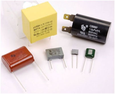
Circuit designers are now experimenting with capacitor based power supply due to its low cost and light weight features. Unlike resistive type power supply, heat generation and power loss is negligible in capacitor power supply. But there are many limitations in capacitor power supply. It cannot give much current to drive inductive loads and since it is connected directly to mains, capacitor breakdown can damage the load. Moreover, there is the risk of shock hazards, if handled carelessly. 
Fig. 1: Image of a Capacitor
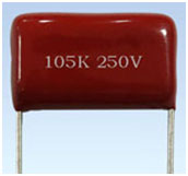
If properly designed and constructed, the capacitor power supply is compact, light weight and can power low current devices. But before selecting the capacitor, it is necessary to determine the current that can be supplied by the capacitor. This note will help you to calculate the current in AC capacitor.
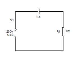
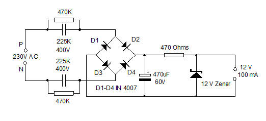
When an AC capacitor and Resistor are connected to AC lines, aconstant current can be maintained through the resistor R1, so long as the rectance of the capacitor is greater than the resistance of the resistor. The current flow then depends on the value of capacitor C1 assuming that V1 is greater than V2. 
Fig. 2: Circuit Diagram For Registor and Capacitor Connection
Now the current through R1 is
IRMS = V1 x Xc
Where Xc is the reactance of the capacitor C1.
Suppose the line voltage V1 is 230 volt at 50 Hz, then IRMS is
IRMS = 230 (2 p 50 C) = 72220 C or IRMS = 70 mA per uF.
Suppose C1 is 105 K /J. It is 1 uF capacitor and it can give 70 mA current theoretically. Similarly a 225 K ( 2.2uF) capacitor can give 159 mA current.
Let us see the current in a 225 K capacitor.
First of all we have to calculate the Rectance (X) of the capacitor.
X = 1 / 2 p f C
Here f is the 50Hz mains frequency and C is the capacitance of 225K capacitor in Farads. As you know 1 microfarad (uF) is equal to 1/ 10 6 Farads.
Therefore 2.2 uF is 2.2 x 1/ 10 6 = 2.2 x 10 – 6
So X = 1 / 2 p x 50 x C x 10 – 6 = 1447.6 Ohms or 1.44 Kilo Ohms.
Now let us see the current that can be delivered by the 225 K capacitor.
Current I in mA = Volt / Rectance in Kilo Ohms
Here supply voltage is 230 volts and reactance X of 225 K capacitor is 1.44 K
So 230 / 1.44 = 159 mA
Do not use this power supply for testing prototypes or as battery charger. Do not construct this on Bread board. Use common PCB.
So, theoretically a 225 K capacitor can give 159 milli ampere current but practically we can expect only 100- 120 mA current because, the current through the capacitor depends on input voltage, reactance of capacitor etc.
If two 225 K capacitors are connected in parallel, current can be doubled.
X and Y rated AC capacitors
There are two classes of AC capacitors, Class X and Y. Class X capacitors are connected from line to line while Y capacitors are connected from line to ground. Another significant difference between these two classes is if an X capacitor fails it does not expose anyone to electrical shock as opposed to a Y capacitor, which upon failure would expose anyone to electrical shock. Of the two types of interference capacitors the Class Xis more common with the Class X2 being the most common.

Fig. 3: Image showing Different types of Capacitors
Class X capacitors are subdivided into 3 types, class X1, X2 and X3. The difference is in the peak voltage rating for the capacitors. Class Y capacitors are divided into 4 types, Y1, Y2, Y3 and Y4. Like X capacitors the different classes have different peak voltage ratings.
Most Important : Prevent Shock Hazards

1. Capacitor power supply is directly connected to mains and there is no galvanic isolation. Front end of the power supply is at mains lethal potential.
2. Do not touch or trouble shoot when it is connected to mains.
3. Always use insulated screw driver and tester.
4. It is better to place a rubber sheet or wooden plank on the floor so that foot rests on the insulator while working with AC circuits.
5. Always keep the left hand behind the body while testing live wires.
6. Always enclose the circuit is a shock proof case. Do not keep the case opened.
7. These forms of power supply should be constructed only by experienced persons to avoid shock hazards.