This is a home automation project using an NEC IR remote to control appliances. In this project a car stereo remote or a general DVD remote or any remote control using NEC key coding format will be used to control switching electrical and electronics appliances. This project is a demonstration of a simple home automation application where the user can switch remote appliances ON or OFF with a handheld IR remote. In the project, four bulbs will be switched ON or OFF using any regular NEC IR remote.
Using an NEC IR remote has the advantage that its receiver needs only one pin of microcontroller to interface and control signal for large number of devices can be sent using NEC encoding scheme on a single microcontroller pin. The NEC format for remote controls is quite popular in India and one of such remote can be easily purchased anywhere at minimal cost of 14 – 16 rupees ($0.205-$0.235). The IR remotes are obviously wireless and easily available too.

Fig. 1: Prototype of NEC IR Remote based Home Automation System
The project is built on Arduino UNO and any AC appliance operating at 220V – 240V 50Hz AC supply can be interfaced and controlled by the project. The Arduino UNO is the programmable unit and implements the embedded program to facilitate automation. The Arduino IDE is used to write the program code for decoding NEC signal and accordingly generate digital output to control the relays switching appliances ON or OFF. The program code is burnt to the board using AVR Dude.
COMPONENTS REQUIRED
• Arduino UNO
• NEC IR remote
• TSOP 1738 sensor
• 16×2 LCD
• 12v Relay
• BC 547 transistor
• 1K ohm resisters -7
• Voltage regulator -7805
• LED -5mm RED- 2
• Wire to carry 2A,230v AC
• Two pin Plug
• Three pin holder
• Bulb holder-4pcs
• 220v-240v AC bulb

Fig. 2: Block Diagram of NEC IR Remote based Home Automation System
CIRCUIT CONNECTIONS
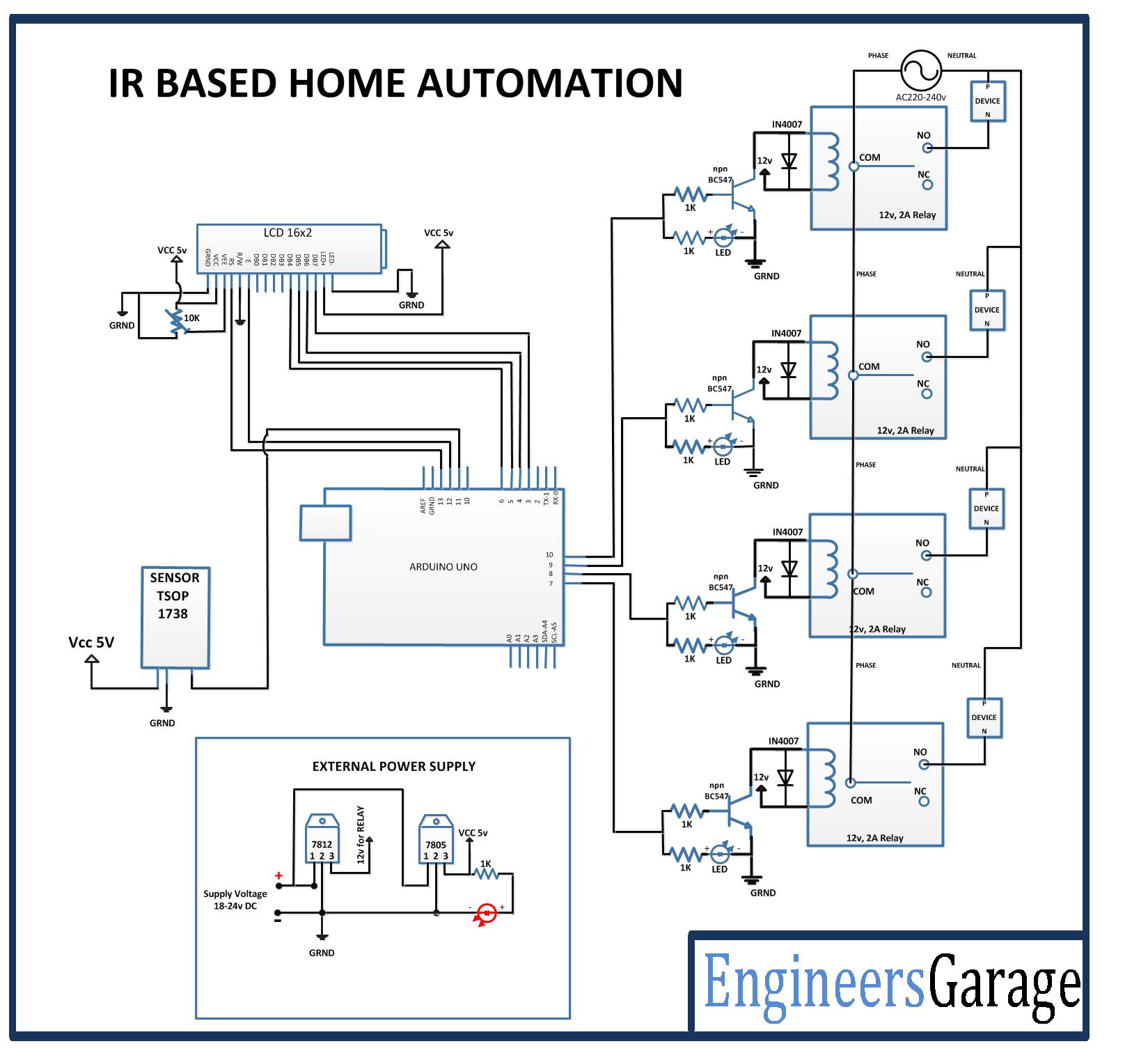
The circuit is based on Arduino UNO. The different sections of the circuit will be interfaced with the Arduino board. The circuit will have the following sections – :
Power Supply – The power to the circuit will be supplied by 18V-24V battery. The Arduino board, LCD display and TSOP 1738 IR sensor need 5V supply while the relays will need 12V DC supply. The supply from the battery will be regulated to 5V and 12V using 7805 and 7812 ICs. The pin 1 of both the voltage regulator ICs will be connected to the anode of the battery and pin 2 of both ICs will be connected to ground. The respective voltage outputs will be drawn from pin 3 of the respective voltage regulator ICs.
TSOP 1738 IR Sensor – The TSOP 1738 IR sensor will be used to receive the data from the NEC IR remote. The sensor has three terminals of which pin 1 will be connected to 5V VCC and pin 2 will be connected to the ground. The digital output from the sensor will be received from pin 3 which will be connected to the pin 11 of Arduino board.

Fig. 3: Table listing circuit connections between Arduino Uno and Character LCD
The standard open-source library for interfacing LCD with Arduino UNO is used in the project. The library works as expected and needs no changes or modifications.
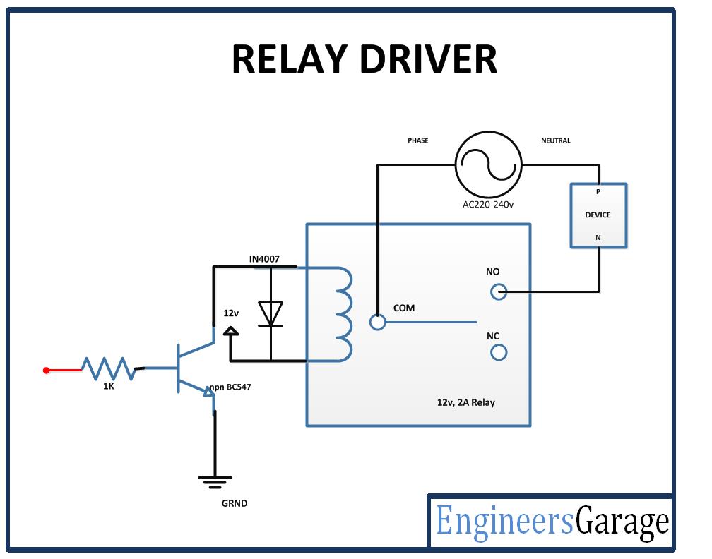
Relays – The 12V 2A relays are used to switch the AC appliances ON or OFF in the project. The relays are connected to the pins 7, 8, 9 and 10 of Arduino board via BS547 transistor circuits connected in a common emitter configuration. The phase wire from the AC supply is provided at the COM terminal of the relays. When a HIGH logic is received at the interfaced microcontroller pins, the COM point switches from NC to NO point where a relay short-circuits the phase with the neutral wire switching the supply to the appliance ON.
NEC IR remote – A regular NEC IR remote is used in the circuit. The Power button and keys ONE, TWO, THREE and FOUR of the IR remote will be used for the following functions -:

Fig. 4: Table listing NEC Remote buttons and their functions
How the Project Works
When the project is powered on, initial messages are flashed on the LCD display and the microcontroller is set ready to read IR keys decoded by the TSOP 1738 IR sensor. A LOW logic is passed to the microcontroller pins connecting the relays therefore keeping the appliances switched OFF by default.
The NEC IR remote used in the project sends 28-bit long encoded IR keys. NEC IR remote uses a transmission protocol known as pulse distance encoding of the message bits, where each message packet is 562.5us in length and the 38KHz carrier frequency is about 26.3us in length. Logical “0” consists of burst pulses of 562.5us and followed by a 562.5us space. So the total time is 1.125ms while Logical “1” consists of burst pulses of 562.5us and followed by a 16875ms space. So the total time is 2.25ms.

Fig. 5: Signal Diagram of NEC IR Transmission Frame

Fig. 6: Table listing NEC Remote buttons and respective NEC signal encoding
The IR remote keys are read by the TSOP 1738 IR sensor and transmitted to the Arduino board. The Arduino has the program code to detect the IR key received and accordingly switch digital output to the pins connecting with the relays.
When the ONE button is pressed on the IR remote, the IR key transmitted is 0x1FE50AF. When the program code reads the stated key, it switches the device connected at pin 10 ON by sending a HIGH logic to trigger the relay to NO point. If the device is already ON which is traced by a Boolean “a”, device connected at pin 10 is switched OFF by sending a LOW logic to trigger the relay to NC point.
When the TWO button is pressed on the IR remote, the IR key transmitted is 0x1FED827. When the program code reads the stated key, it switches the device connected at pin 7 ON by sending a HIGH logic to trigger the relay to NO point. If the device is already ON which is traced by a Boolean “b”, device connected at pin 7 is switched OFF by sending a LOW logic to trigger the relay to NC point.
When the THREE button is pressed on the IR remote, the IR key transmitted is 0x1FEF807. When the program code reads the stated key, it switches the device connected at pin 8 ON by sending a HIGH logic to trigger the relay to NO point. If the device is already ON which is traced by a Boolean “c”, device connected at pin 8 is switched OFF by sending a LOW logic to trigger the relay to NC point.
When the FOUR button is pressed on the IR remote, the IR key transmitted is 0x1FE30CF. When the program code reads the stated key, it switches the device connected at pin 9 ON by sending a HIGH logic to trigger the relay to NO point. If the device is already ON which is traced by a Boolean “d”, device connected at pin 9 is switched OFF by sending a LOW logic to trigger the relay to NC point.
When the Power button is pressed on the IR remote, the IR key transmitted is 0x1FE609F. When the program code reads the stated key, it switches all the devices ON while if devices are already ON, it switches the devices OFF.
Programming Guide
A setup() function is declared in which the baud rate for serial transmission of data to the LCD is set to 9600 bits per second using Serial.begin() function. The LCD is initialized using lcd.begin() function and microcontroller is set ready to receive IR keys using irrecv.enableIRIn() function. The pins connecting with the relays are set to digital output using PinMode() function. Some initial messages are flashed on the LCD display indicating the purpose of the project and default OFF status of all the devices.
The loop() function is called in which the received IR keys are detected using irrecv.decode() function. If the IR key received is 0x1FE50AF corresponding to ONE button, and if Device 1 is OFF traced by checking variable “a” set to 0, a HIGH logic is sent to the pin 10 using DigitalWrite() function and variable “a” is set to 1. If Device 1 is ON traced by checking variable “a” set to 1, a LOW logic is sent to the pin 10 using DigitalWrite() function and variable “a” is set to 0. The current status of Device 1 is updated on the LCD.
If the IR key received is 0x1FED827 corresponding to TWO button, and if Device 2 is OFF traced by checking variable “b” set to 0, a HIGH logic is sent to the pin 7 using DigitalWrite() function and variable “b” is set to 1. If Device 2 is ON traced by checking variable “b” set to 1, a LOW logic is sent to the pin 7 using DigitalWrite() function and variable “b” is set to 0. The current status of Device 2 is updated on the LCD.
If the IR key received is 0x1FEF807 corresponding to THREE button, and if Device 3 is OFF traced by checking variable “c” set to 0, a HIGH logic is sent to the pin 8 using DigitalWrite() function and variable “c” is set to 1. If Device 3 is ON traced by checking variable “c” set to 1, a LOW logic is sent to the pin 8 using DigitalWrite() function and variable “c” is set to 0. The current status of Device 3 is updated on the LCD.
If the IR key received is 0x1FE30CF corresponding to FOUR button, and if Device 4 is OFF traced by checking variable “d” set to 0, a HIGH logic is sent to the pin 9 using DigitalWrite() function and variable “d” is set to 1. If Device 4 is ON traced by checking variable “d” set to 1, a LOW logic is sent to the pin 9 using DigitalWrite() function and variable “d” is set to 0. The current status of Device 4 is updated on the LCD.
If the IR key received is 0x1FE48B7 corresponding to POWER button, and variable “e” set to 0, a HIGH logic is sent to the pins 7, 8, 9 and 10 using DigitalWrite() function and variable “e” is set to 1. If all devices are ON traced by checking variable “e” set to 1, a LOW logic is sent to the pins 7, 8, 9 and 10 using DigitalWrite() function and variable “e” is set to 0. The current status of all the devices is updated on the LCD.
In the end of the loop() function, the controller is configured to receive the next IR key by calling the irrecv.resume() function.
Project Source Code
###
#include <IRremote.h> int RECV_PIN = 11; IRrecv irrecv(RECV_PIN); #include <LiquidCrystal.h>//import the LCD library LiquidCrystal lcd(13, 12, 6, 5, 4, 3);// Pins used for RS,E,D4,D5,D6,D7 decode_results results; int a=0,b=0,c=0,d=0,e=0,spd=0; //used for key press or not int ONE=10; //Digital pin 6 isS used to ON relay 1 int TWO=7; //Digital pin 7 is used to ON relay 2 int THREE=8; //Digital pin 8 is used to ON relay 3 int FOUR=9; //Digital pin 9 is used to ON relay 4 void setup() { Serial.begin(9600); lcd.begin(16,2);//LCD 16x2 initialization irrecv.enableIRIn(); // Start the receiver pinMode(ONE, OUTPUT);// Set pim 6 as OUTPUT pinMode(TWO, OUTPUT);// Set pim 7 as OUTPUT pinMode(THREE, OUTPUT); // Set pim 8 as OUTPUT pinMode(FOUR, OUTPUT); // Set pim 8 as OUTPUT lcd.setCursor(0,0); //Initially set the cursor position of LCD to 1st Columb 1st row. lcd.print("Engineers Garage");//After initialising print data lcd.setCursor(0,1); //Initially set the cursor position of LCD to 1st Columb 2nd row. lcd.print(" "); //print blank to clear all the data on LCD delay(3000); lcd.setCursor(0,0); lcd.print(" IR Based Home "); lcd.setCursor(0,1); lcd.print(" Automation "); delay(3000); lcd.setCursor(0,0); lcd.print("D1:OFF D2:OFF"); //Initially dispaly all are OFF lcd.setCursor(0,1); lcd.print("D3:OFF D4:OFF");//Initially dispaly all are OFF } void loop() { if (irrecv.decode(&results)) { // IF BUTTON 1 PRESSED .... if(results.value==0x1FE50AF && a==0){ // Checking the received number if found with the given condition a=1; // "a" variable used to checked if button is pressed or not. digitalWrite(ONE,1); //if pressed send HIGH value to the pin number 6 lcd.setCursor(3,0); lcd.print("ON "); //Display ON in the location 1st ROW and 3rd COLUMB } else if (results.value==0x1FE50AF && a==1) {// IF BUTTON 1 PRESSED .... a=0; digitalWrite(ONE,0); lcd.setCursor(3,0); lcd.print("OFF"); } else if (results.value==0x1FED827 && b==0) {// IF BUTTON 2 PRESSED .... b=1; digitalWrite(TWO,1); lcd.setCursor(13,0); lcd.print("ON "); } else if (results.value==0x1FED827 && b==1) {// IF BUTTON 2 PRESSED .... b=0; digitalWrite(TWO,0); lcd.setCursor(13,0); lcd.print("OFF "); } else if(results.value==0x1FEF807 && c==0) { // IF BUTTON 3 PRESSED .... c=1; digitalWrite(THREE,1); lcd.setCursor(3,1); lcd.print("ON "); } else if (results.value==0x1FEF807 && c==1) {// IF BUTTON 3 PRESSED .... c=0; digitalWrite(THREE,0); lcd.setCursor(3,1); lcd.print("OFF "); } else if (results.value==0x1FE30CF && d==0) {// IF BUTTON 4 PRESSED .... d=1; digitalWrite(FOUR,1); lcd.setCursor(13,1); lcd.print("ON "); } else if (results.value==0x1FE30CF && d==1) {// IF BUTTON 4 PRESSED .... d=0; digitalWrite(FOUR,0); lcd.setCursor(13,1); lcd.print("OFF "); } else if (results.value==0x1FE48B7 && e==0 ) {// IF POWER BUTTON PRESSED .... e=1; digitalWrite(ONE,1); digitalWrite(TWO,1); digitalWrite(THREE,1); digitalWrite(FOUR,1); lcd.setCursor(0,0); lcd.print("D1:ON D2:ON "); //Initially dispaly all are OFF lcd.setCursor(0,1); lcd.print("D3:ON D4:ON ");//Initially dispaly all are OFF } else if (results.value==0x1FE48B7 && e==1) {// IF POWER BUTTON PRESSED ..... e=0; digitalWrite(ONE,0); digitalWrite(TWO,0); digitalWrite(THREE,0); digitalWrite(FOUR,0); // digitalWrite(PWM,0); lcd.setCursor(0,0); lcd.print("D1:OFF D2:OFF"); //Dispaly all are OFF lcd.setCursor(0,1); lcd.print("D3:OFF D4:OFF");//Dispaly all are OFF } /* else if(results.value==0x1FE609F) {// IF VOLUME+ BUTTON PRESSED .... if(spd<4) { spd++; x=x+50; analogWrite(PWM, x); lcd.setCursor(8,0); lcd.print(spd); }} else if(results.value==0x1FEA05F) { if(spd>0) {// IF VOLUME- BUTTON PRESSED .... spd--; x=x-50; analogWrite(PWM, x); lcd.setCursor(8,0); lcd.print(spd); }}*/ irrecv.resume(); // Receive the next value } }###
Circuit Diagrams
Project Video
Filed Under: Electronic Projects
Filed Under: Electronic Projects

Questions related to this article?
👉Ask and discuss on EDAboard.com and Electro-Tech-Online.com forums.
Tell Us What You Think!!
You must be logged in to post a comment.