You may have seen so many land rover projects on different websites or even on multyremotes.com as moon-walker and robo-vehicle. Most probably they are remote controlled (either IR or RF) or they may be automatic guided vehicles (AGV). This is also remote controlled land rover but as a remote control one can use his cell phone. That means he can move the land rover by sending different commands from his cell phone. Not only that, he can control it from anywhere in the world (of course where GSM / CDMA network is available).
This concept is taken from military application where such land rover works as Unmanned Guided vehicle (UGV) for spy operations, mine diffuser, bomb detector etc. in such application the movements of land rover can be controlled from very far remote and safe place (as there is practically no limitation on operating range)
Here I have develop very simple application in which the land rover moves forward, backward and takes left or right turn as per commands given from any cell phone but one can develop any interesting application over this platform like given above.
Let us start with mechanical assembly of land rover.
Mechanical Assembly: –

As shown in above figure four wheels are attached with chassis made up of any metal (like iron). Shaft of two DC motors (around 150 RPM or more) are directly coupled with real wheels. So as both motors rotate CW, the land rover moves forward. And as both motors rotate CCW, it will move backward. to turn it left right DC motor rotates and to turn it right left DC motor rotates. Also it will take forward-left & forward-right turn as well as backward-left & backward-right turn if required. For that, either of the motors (left or right) is rotated CW or CCW. For example if left motor rotates CW, land rover will take forward-right turn and if it rotates CCW then backward-right turn. Similarly for right DC motor.
Now let us see the block diagram of system
System Block diagram
System Block diagram: –

The major building blocks are cell phone, DTMF decoder, micro-controller, DC motor driver circuits.
Cell phone: – This is very first and the most important part of the system because due to this only the entire system is activated and works. It will receive the signals from another cell phone and gives them as input to DTMF decoder. First the system is activated by calling the SIM card number inside the phone. Afterwards it will receive DTMF code signals dialed from another cell phone and give it to DTMF decoder.
DTMF decoder: – The function of this block is self understood. It will take DTMF input given by cell phone decode it and gives 4-bit digital output to micro controller. It also generates an interrupt every time when it gives digital output
Micro-controller: – You can call this block as the heart of entire system because it actually performs all the controlling actions. Depending upon the code given by DTMF decoder it will move the rover forward, backward, left or right by rotating both DC motors
DC Motor driver: – It receives actuating signals from micro controller in terms of high / low logic, amplifies (current) it and rotates 2 DC motors in both directions
Land Rover Circuit
Land rover circuit
I have divided complete circuit into three major blocks
- DTMF decoder
- Micro controller
- DC motor driver
DTMF decoder: –

As shown in figure it is made up form readily available MT8870 chip that is widely used for DTMF based application. It receives DTMF tones and generates 4-bit digital output corresponding to received DTMF signal of digits 0 – 9 and other signals (like *, # etc) also. It receives input form cell phone to its pin no 2. It amplifies it through internal op-amp amplifier. If it receives valid DTMF tone, it will produce pulse output on StD (pin no 15). This is indicated by green LED connected as shown. The 4-bit digital output is latched on pins 11 – 14 and that is given to micro controller. The StD output is also given to interrupt pin of micro controller through transistor that will generate negative pulse every time when DTMF signal is received. This negative pulse will generate an interrupt. All the movements of robotic arm are controlled by cell phone digit switches 1 to 8. The 4 bit digital output corresponding to these switches form MT8870 are as given here
|
Keypad switch on cell phone |
4 bit digital output |
|||
|
D |
C |
B |
A |
|
|
1 |
0 |
0 |
0 |
1 |
|
2 |
0 |
0 |
1 |
0 |
|
3 |
0 |
0 |
1 |
1 |
|
4 |
0 |
1 |
0 |
0 |
|
5 |
0 |
1 |
0 |
1 |
|
6 |
0 |
1 |
1 |
0 |
|
7 |
0 |
1 |
1 |
1 |
|
8 |
1 |
0 |
0 |
0 |
Micro-controller
Micro-controller: –

As shown in figure a 40 pin, 8-bit micro controller 89C51 is used for controlling purpose. It receives 4-bit digital output from DTMF decoder on its port P1 pins P1.0 – P1.3. And interrupt signal is given to P3.3 (external interrupt 1) pin. It drives two DC motors through port P2 pins P2.0 – P2.3. A 12 MHz crystal with two 33pf capacitors is connected to crystal pins (18 & 19) to provide basic clock signal to micro controller. One push button switch (RST) in parallel with 100nF capacitor forms power on reset circuit to reset the micro controller. it will control the motion of land rover depending upon the code it receives from DTMF decoder as given in table
|
4 bit digital input |
Hex code |
Movement – controlling action |
|||
|
D |
C |
B |
A |
||
|
0 |
0 |
1 |
0 |
F2h |
starts moving forward |
|
0 |
1 |
0 |
0 |
F4h |
Take a left turn |
|
0 |
1 |
0 |
1 |
F5h |
Stop moving |
|
0 |
1 |
1 |
0 |
F6h |
Take a right turn |
|
1 |
0 |
0 |
0 |
F8h |
Start moving backward |
DC Motor driver
DC Motor driver: –
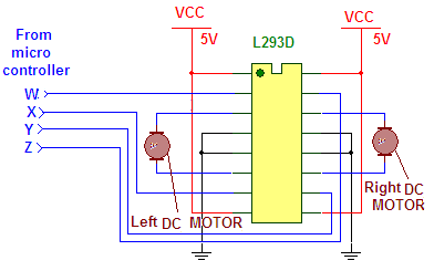
As shown in figure L293D is quadruple H-Bridge driver chip that is widely used for DC motor and stepper motor driver applications. It receives inputs from micro controller as shown on its input pins 2,7,10 & 15 and rotates two DC motors in either direction as per given table
|
W (pin no 2) |
X (pin no 7) |
Y (pin no 10) |
Z (pin no 15) |
Motor |
|
1 |
0 |
0 |
0 |
left motor rotates CW |
|
0 |
1 |
0 |
0 |
left motor rotates CCW |
|
0 |
0 |
1 |
0 |
Right motor rotates CW |
|
0 |
0 |
0 |
1 |
Right motor rotates CCW |
So to move the land rover forward or backward – left or right one has to send following data on port
|
Motion |
W (P2.0) |
X (P2.1) |
Y (P2.2) |
Z (P2.3) |
data |
|
Move forward – rotate both motors CW |
1 |
0 |
1 |
0 |
05h |
|
Move backward – rotate both motors CCW |
0 |
1 |
0 |
1 |
0Ah |
|
Turn left – rotate right motor CW |
0 |
0 |
1 |
0 |
04h |
|
Turn right – rotate left motor CW |
1 |
0 |
0 |
0 |
01h |
Land Rover C Program
land rover C program
The program shown in the code tab is very simple. It is written in embedded C language and compiled using KEIL (IDE). Initially in the main function, the ports are initializes as input or output. Then external interrupt 1 is enabled. Then the program waits in a continuous loop to for any input available from DTMF decoder. As interrupt arrives the program jumps to interrupt function and get the code. Then again it returns to main function and compares the code. As the match is found, it will send data 05h, 0Ah, 01h or 04h on port P2 to move rover forward, backward, left or right.
int1 function simply gets the input on port P1 from DTMF decoder
keydly function is for generating random delay when interrupt arrives to stop multiple interrupts
Project Source Code
###
#include<reg51.h>
unsigned char data byt=0xFF;
void keydly()
{
int a,b;
for(a=0;a<50;a++)
for(b=0;b<1000;b++);
}
void int1() interrupt 2
{
byt=P1;
EA=0;
keydly();
}
void main()
{
P2=0x00;
P1=0xFF;
back:IE=0x84;
byt=0xFF;
while(byt==0xFF);
switch(byt)
{
case 0xF2:
P2=0x05;
break;
case 0xF4:
P2=0x04;
break;
case 0xF5:
P2=0x00;
break;
case 0xF6:
P2=0x01;
break;
case 0xF8:
P2=0x0A;
break;
}
goto back;
}###
Filed Under: Electronic Projects

Questions related to this article?
👉Ask and discuss on Electro-Tech-Online.com and EDAboard.com forums.
Tell Us What You Think!!
You must be logged in to post a comment.