We can control the speed of the single phase DC Motor with ease by using microcontroller and proper driving mechanism.In industries mostly coil based analog variable frequency drive is used. Because of this type of variable frequency drive there are problem rising like over current, short circuit, over voltage, under voltage, under frequency which results in unwanted tripping of the devices.We can replace this coil based analog variable frequency type with microcontroller based speed controlling mechanism. Because of this type of speed controlling, we can accurately control the speed of DC motor in operation. In addition to this, this type of controlling comparatively cheaper, reliable and accurate .It requires less maintenance and it is more convenient in use.

Fig. 1: Prototype of 8051 Microcontroller based Mobile Phone controlled DC Motor Controller
Aim of this project is to control speed of dc motor using commands sent from mobile phone. As speed of dc motor is dependent on duration of input voltage, by changing the duration we can control the speed of the single phase dc motor.
BLOCK DIAGRAM

Fig. 2: Block Diagram of 8051 Microcontroller based Mobile Phone controlled DC Motor Controller
DESCRIPTION OF BLOCK DIAGRAM:-
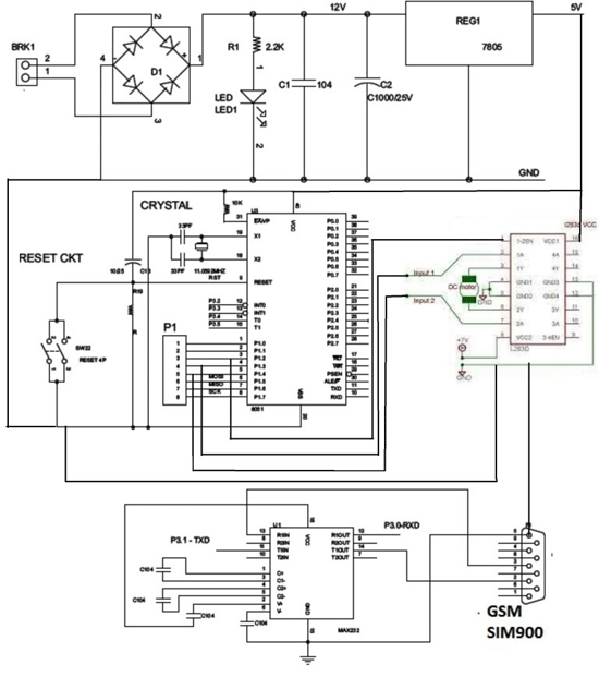
· AT89S52 controller of 8051family from ATMEL is the heart of the system which works on 5V DC supply. It is used to control the operation of whole system.
· GSM has been provided to receive the commands sent from mobile phone and send to the controller AT89252.
· LCD displays the received command and Speed of DC motor.
· Motor Driver IC L293 drives DC motor as per the signals received from controller.
LIST OF COMPONENTS :-
1. 230V-12V STEP DOWN Transformer
2. Bridge Rectifier
3. 1000 uf Capacitor
4. 100 uf Capacitor
5. 7805 Voltage Regulator IC
6. 11.0592 MHz crystal
7. 33 pf Capacitors (2 Nos.)
8. 8.2k resistor
9. 10uf Capacitor
10. Push to ON switch
11. 5 mm LEDs
12. AT89S52 Controller
13. 16*2 LCD
14. DC Motor

Fig. 3: Image of LCD Module connected to 8051 Microcontroller based DC Motor Controller
Concept of variable speed drives:
· DC MOTOR :-
· Any variable speed electrical drive system comprises of following components:
· An electronic actuator- the controller.
· Driving electrical machines –motor.
· A driven machine- pumps fan, blower, compressor…..
The task of a variable speed electrical drive is to convert the electrical power supplied by the mains into mechanical power with a minimum loss. To achieve an optimum technological process, the drive must be variable in speed. This will sleeplessly adjust the speed of the driven machine. This is ensured by the low loss control using solid state technology in electronic controllers. The controllers are connected to mains supply and the electrical machine as shown in figure.
The solid-state devices, which convert the AC supply, were first used as variable speed devices, in DC technology. Using these devices the armature voltage of a dc motor and therefore the speed can be adjusted,almost without losses and over a wide range of speed.
· Although a far greater percentage of electric motors in service are AC motors, the DC motor is of considerable industrial importance. The principal advantage of a DC motor is that its speed can be changed over a wide range by a variety of simple methods. Such a fine speed control is generally not possible with AC motors. In fact, fine speed control is one of the reasons for the strong competitive position of DC motors in the modem industrial applications.
· Voltage control method for DC MOTOR:-
· In this method, the voltage source supplying the field current is different from that which supplies the armature. This method avoids the disadvantages of poor speed regulation and low efficiency as in armature control method. However, itis quite expensive. Therefore, this method of speed control is employed for large size motors where efficiency is of great importance.
(i) Multiple voltage control. In this method, the shunt field of the motor is connected permanently across a-fixed voltage source. The armature can be connected across several different voltages through suitable switchgear. In this way, voltage applied across the armature can be changed. The speed will be approximately proportional to the voltage applied across the armature. Intermediate speeds can be obtained by means of a shunt field regulator.
(ii) Ward-Leonard system. In this method, the adjustable voltage for the armature is obtained from an adjustable-voltage generator while the field circuit is supplied from separate source.
Advantages:-
(a) The speed of the motor can be adjusted through a wide range withoutresistance losses which results in high efficiency.
(b) The motor can be brought to a standstill quickly, simply by rapidlyreducing the voltage of generator G. When the generator voltage is reducedbelow the back EMF of the motor, this back EMF sends current throughthe generator armature, establishing dynamic braking. While this takesplace, the generator G operates as a motor driving motor A which returnspower to the line.
(c) This method is used for the speed control of large motors when a DC supply is not available.The disadvantage of the method is that a special motor-generator set is requiredfor each motor and the losses in this set are high if the motor is operating underlight loads for long periods
· ADVANTAGE OF SYSTEM :-
1) The project is controller based hence external components are minimum project works automatically you don’t require man power to do the speed controller it is accurate and reliable.
2) LCD displays frequency value as well as on off status.
3) The motor of excess RPM can be used for less RPM by use of variable frequency drive.
4) The skilledlabor is not required in our proposed system.
5) Low cost system, providing maximum automation.
6) Low maintenance and low power consumption.
· DISADVANTATG OF SYSTEM:-
1) The project is controller based hence you require skilled to develop the project.
2) To write the software also you require skilled person.
3) For trouble shooting of project requires special training of engineer’s.
4) Design testing repair of system
5) No self-test system to detect malfunction of sensors.
6) Requires uninterrupted power supply.
7) LCD display is not good for outdoor application
· APPLICATION OF SYSTEM
· There are many applications of speed control of DC motor for winding machines robotic movement like lift locomotives works on motor.Domestic equipment’s are also working on motor.
· Wherever direction change and speed control isrequired the project is useful.
· FUTURE OF THE PROJECT:-
· The present project capacity is only 1/2hp or 1hp 1 phase DC motor drive. We can put higher rating switching device and higher rating heat sink for higher capacity of the drive. We can increase accuracy using PID controolers. RPM of motor can be displayed on LCD. We can measure temperature of motor and display on LCD. We can give alarm and tripping facility for protecting the devices.
Project Source Code
###


#include"main.h"
#include "lcd.h"
unsigned char str2[15];
static unsigned char count = 0;
unsigned char PercentageOfModulation = 10;
unsigned char a,b,i=0,j=0,k=0,m;
//FUNCTIONS
void main(void)
{
EA=1;ES=1;
Delay(100);
LCDInitialize();
LCDClear();
LCDWriteString("WELCOME TO MOTOR");
LCDRow2();
LCDWriteString(" SPEED CONTROL");
Delay(100);
MainSystemInitialize();
/*RotateMotorClockwise();
TR0 = 1;
for(;;);*/
for(;;);
}
static void MainSystemInitialize(void)
{
MotorInitialize();
PWM_BIT = 0; //output bit
Timer0_Initialize();
}
static void Timer0_Initialize(void)
{
TMOD &= 0xF0;
SCON=0x50;
TH1=0xFD;
TL0 = 0x05;
EA = 1;
TR1=1;
}
static void Timer0ISR(void) interrupt 1
{
if(count++ == 100)
count = 0;
if(count < PercentageOfModulation)
PWM_BIT = 1;
else
PWM_BIT = 0;
}
void mesgrecvd(void)
{
if(RI)
{
RI = 0;
b= SBUF;
while(b=='*')
{
for(i=0;i<12;i++)
    {
     while(RI==0);
     str2[i]=SBUF;
     RI=0;
    }
if(str2[6]=='S' && str2[7]=='T' && str2[8]=='A' && str2[9]=='R' && str2[10]=='T')
  {
LCDClear();
LCDWriteString("MOTOR START..");
RotateMotorClockwise();
 TR0 = 1;
 }
if(str2[6]=='S' && str2[7]=='T' && str2[8]=='O' && str2[9]=='P')
{
LCDClear();
LCDWriteString("MOTOR STOP");
StopMotor();
}
if(str2[6]=='U' && str2[7]=='P')
  {
LCDClear();
LCDWriteString("SPEED UP");
PercentageOfModulation=PercentageOfModulation+10;
if (PercentageOfModulation>100)
PercentageOfModulation=100;
RotateMotorClockwise();
    TR0 = 1;
   }
if(str2[6]=='D' && str2[7]=='O' && str2[8]=='W' && str2[9]=='N')
  {
LCDClear();
   LCDWriteString("SPEED DOWN");
PercentageOfModulation=PercentageOfModulation-10;
if (PercentageOfModulation<0)
PercentageOfModulation=0;
RotateMotorClockwise();
    TR0 = 1;
   }
}
}
}

###
Circuit Diagrams
Filed Under: Electronic Projects

Questions related to this article?
👉Ask and discuss on EDAboard.com and Electro-Tech-Online.com forums.
Tell Us What You Think!!
You must be logged in to post a comment.