Solar energy is rapidly gaining notoriety as an important means of expanding renewable energy resources. As such, it is vital that those in engineering fields understand the technologies associated with this area. Our project will include the design and construction of a microcontroller-based solar panel tracking system. Solar tracking allows more energy to be produced because the solar array is able to remain aligned to the sun. This system builds upon topics learned in this course. A working system will ultimately be demonstrated to validate the design. Problems and possible improvements will also be presented.
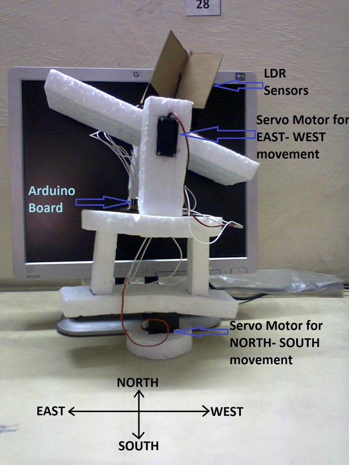
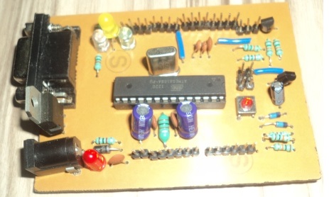
Final Setup of Arduino Based Solar Tracker
AIM OF THE PROJECT
The aim of this solar tracker project is to keep the solar photovoltaic panel perpendicular to the sun throughout the year in order to make it more efficient. The dual axis solar photovoltaic panel takes astronomical data as reference and the tracking system has the capability to always point the solar array toward the sun and can be installed in various regions with minor modifications. The vertical and horizontal motion of the panel is obtained by taking altitude angle and azimuth angle as reference. The fuzzy controller has been used to control the position of DC motors. The mathematical simulation control of dual axis solar tracking system ensures the point to point motion of the DC motors while tracking the sun.
Solar Tracker is a Device which follows themovement of the sun as it rotates from the east to the west every day. The main function of all tracking systems is to provide one or two degrees of freedom in movement. Trackers are used to keep solar collectors/solar panels oriented directlytowards the sun as it moves through the sky every day. Using solar trackers increases the amount of solar energy which is received by the solar energy collector and improves the energy output of the heat/electricity which is generated. Solar trackers can increase the output of solar panels by 20-30% which improves the economics of the solar panel project.
NEED FOR SOLAR TRACKER
The energy contributed by the direct beam drops off with the cosine of the angle between the incoming light and the panel. The table no. 2.1 shows the
Direct power lost (%) due to misalignment (angle i).
Table: Direct power lost (%) due to misalignment (angle i)
|
Misalignment (angle i ) |
Direct power lost (%)=1-cos(i) |
|
|
|
|
00 |
0 |
|
|
|
|
10 |
.015 |
|
|
|
|
30 |
.14 |
|
|
|
|
80 |
1 |
|
|
|
|
23.40 |
8.3 |
|
|
|
|
300 |
13.4 |
|
|
|
|
450 |
30 |
|
|
|
|
750 |
>75 |
|
|
|
The sun travels through 360 degrees east-west a day, but from the perspective of any fixed location the visible portion is 180 degrees during a 1/2 day period. Local horizon effects reduce this somewhat, making the effective motion about 150 degrees. A solar panel in a fixed orientation between the dawn and sunset extremes will see a motion of 75 degrees on either side, and thus, according to the table above, will lose 75% of the energy in the morning and evening. Rotating the panels to the east and west can help recapture these losses. A tracker rotating in the east-west direction is known as a single-axis tracker.
The sun also moves through 46 degrees north-south over the period of a year. The same set of panels set at the midpoint between the two local extremes will thus see the sun move 23 degrees on either side, causing losses of 8.3% A tracker that accounts for both the daily and seasonal motions is known as a dual-axis tracker.Tracker Design
TRACKER DESIGN
A solar tracker is a device that orient photovoltaic array toward the sun. In flat-panel photovoltaic (PV) applications trackers are used to minimize the angle of incidence between the incoming light and a photovoltaic panel. This increases the amount of energy produced by the photovoltaic array.
Here we can use azimuth-altitude dual axis trackers (AADAT). Dual axis trackers extract the maximum solar energy levels due to their ability to follow the sun vertically and horizontally. No matter where the sun is in the sky, dual axis trackers are able to angle themselves to be in direction toward the sun.
A setup of a squared solar panel has two degrees of freedom. Here Two DC motors are used to drive the two rotational degrees of freedom. The motors can mounted directly on the rotation pins of the rotational joints to reduce losses caused by linkages and joints and to avoid using more linkages and mechanism
DC MOTOR AND MOTOR DRIVER
The tracking systems would need to consist of two motors, which control the position of the array, and a control circuit (either analog or digital) to direct these motors. The following sections discuss some possible types of motors that could be used for this type of application.
MATHEMATICAL MODEL
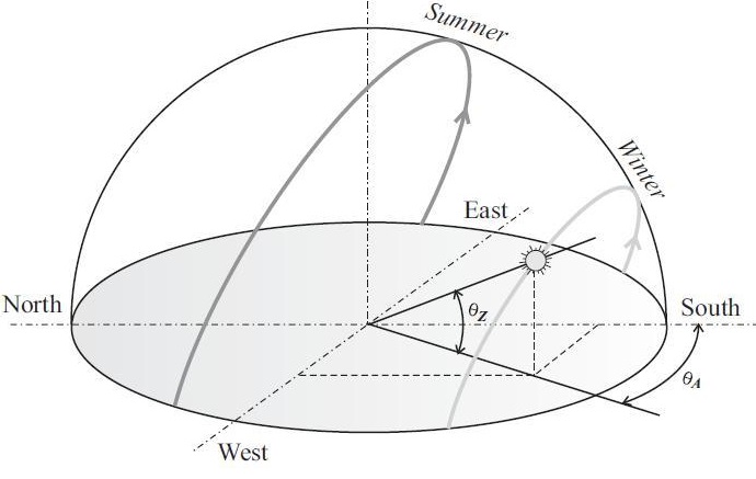
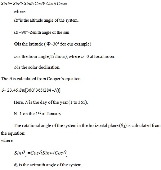
The fig. 3.3 shows a typical behavior for the sun path in December (winter) and June (summer). The rotational angle of the orientation system in the vertical plane can be calculated from the following equation:
Fig. 3.3Typical behavior for the sun path in December (winter) and June (summer).
 System Design
SYSTEM DESIGN
The purpose of a solar tracker is to accurately determine the position of the sun. This enables solar panels to interface to the tracker to obtain the maximum solar radiation. With this particular solar tracker a closed loop system was made.
![]()
Block Diagram of overall system
The electrical system consists of five LDR sensors which provide feedback to a micro controller. This micro controller processes the sensor input and provides two PWM signals for the movement of servo motors.
This servo motor moves the solar panel towards the higher density of solar light. The entire electrical system is powered by a 12volt source power supply.
Initially five different analog values are obtained from LDR’s, and then they are feed to micro controller. Micro controller gives two different PWM signal for the movement of solar panel through servo motor.Sensors
SENSORS
![]()
We are using Five Light Dependent Resistor’s as a sensor. They sense the higher density area of sun light. The solar panel moves to the high light density area through servo motors.
Each LDR is connected to power supply forming a potential devider. Thus any change in light density is proportional to the change in voltage across the LDR’s.
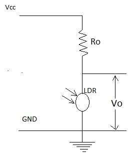
LDR is a passive transducer hence we will use potential divider circuit to obtain corresponding voltage value from the resistance of LDR.
LDRs resistance is inversely proportional to the intensity of light falling on it i.e. Higher the intensity or brightness of light the Lower the resistance and vice versa.
Interfaces:
Input(ADC):
Arduino has an inbuilt 10-bit Analog to Digital converter(ADC), hence it can provide Digital values from 0-1023.(since 2^10=1024). We can also set the ADC reference voltage in arduino, but here we’ll letit use default value.LDR’s has two pins, and to get voltage value from it we use potentialdivider circuit.In potential divider we get Vout corresponding to resistance of LDRwhich in turn is a function of Light falling on LDR. The higher the intensity of light, lower the LDR resistance and hencelower the Output voltage (Vout)And lower the light intensity, higher the LDR resistance and hencehigher the Vout.
Output(PWM):
Arduino has a 8-bit PWM generator, so we can get up to 256 distinct PWM signal. To drive a servo we need to get a PWM signal from the board, this isusually accomplished using timer function of the microcontroller butarduino makes it very easy.Arduino provides a servo library in which we have to only assign servoangle (0-1800) and the servo rotates by that angle, all the PWMcalculations are handled by the servo library and we get a neat PWMsignal according to the desired angle.
ARDUINO SEVERINO BOARD:
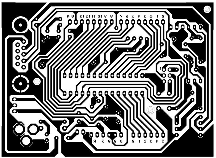
 PCB File
Final Project
You may also like:


Project Source Code
###
# includeServo servo1;Servo servo2;int pos1=0;int pos2=0;int up=0;int down=0;int right=0;int left=0;int centre=0;int ldr1=0;int ldr2=0;int ldr3=0;int ldr4=0;int ldr5=0;void setup (){servo1.attach(10);servo1.write(90);servo2.attach(9);servo2.write(90);pinMode(ldr1, INPUT);pinMode(ldr2, INPUT);pinMode(ldr3, INPUT);pinMode(ldr4, INPUT);pinMode(ldr5, INPUT);}void loop (){pos1=servo1.read();pos2=servo2.read();int up= analogRead(ldr1);int down= analogRead(ldr2);int centre= analogRead(ldr3);int right= analogRead(ldr4);int left= analogRead(ldr5);//for conrol of vertical i.e. up-down(east-west) positionif (up>centre << down{servo1.write(pos1+1);delay(10);}else if (down>centre << up{servo1.write(pos1-1);delay(10);}else{servo1.write(pos1);delay(10);}//for control of horizontal i.e.right-left(south-north) positionif (right>centre << left{servo2.write(pos2+1);delay(10);}else if (left>centre << right{servo2.write(pos2-1);delay(10);}else{servo2.write(pos2);delay(10);}###
Circuit Diagrams
Filed Under: Electronic Projects

Questions related to this article?
👉Ask and discuss on Electro-Tech-Online.com and EDAboard.com forums.
Tell Us What You Think!!
You must be logged in to post a comment.