The project presented here is very nice, interesting and easy to build. Most of you have seen a multicolor optical light fountain. There is a bunch of pieces of optical fiber cables and multicolor LEDs. The LED light is injected into this optical fiber cable bundle from one side and on the other side, you can see the light coming out that looks like an illuminated dot and this complete structure looks like a multicolor light fountain.
In this project, I have replaced the multicolor LEDs with RGB LED and I am controlling this RGB LED through touch sensor using arduino. We know RGB LED can generate most of the colors. So here RGB LED generates three primary (RED, GREEN, BLUE) and three secondary colors (YELLOW, CYAN, MEGANTA) when this different color light passes through optical fiber cables it makes a multicolor light fountain. The color of this light fountain can be changed through simple touch. Means, just by touching, the color of light fountain changes from RED to GREEN or from BLUE to YELLOW or any other. This creates a wonderful visual effect.
The touch plate is used as a touch sensor that gives input to arduino when anyone touches it. And arduino controls RGB LED and generates different color every time when it gets touch input.
CIRCUIT DESCRIPTION
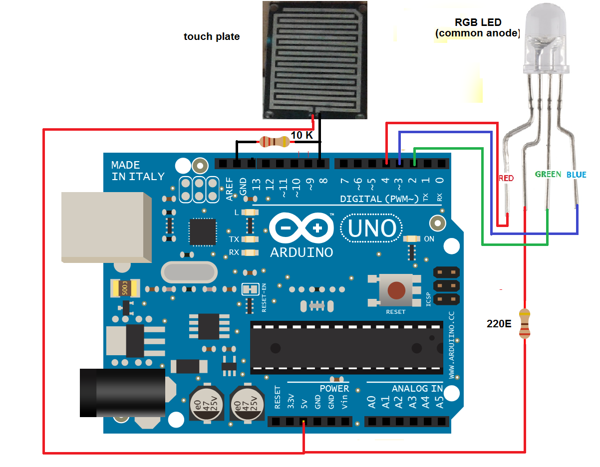
• A touch plate has two contact terminals. One is connected to 5 V output from Arduino board and another is connected to digital pin 8. This pin is also pulled down through 10 K resistor.
• The RGB LED is placed inside the light fountain. Its common anode type RGB LED
• Its common anode terminal is connected to 5 V supply from the board through a current limiting resistor. Three cathode terminals red, green and blue are connected to arduino digital pins 2, 3 and 4 respectively.
Here is the snap of circuit arrangement.

Fig. 1: Prototype of Arduino based Touch controlled Light Fountain
CIRCUIT OPERATION
• First, the Arduino board is given supply from laptop/computer through USB.
• Initially, the RGB LED is off. So no color from the light fountain. The digital input pin 8 is connected to ground so it gets logic 0 input.
• Now when anyone touches the plate, it gives logic 1 input to pin 8. This will turn ON red color in RGB LED. So the light fountain illuminates red.
• Again when anyone touches plate 2nd time, it makes green color ON and red color OFF. So now light fountain turns green.
• Similarly, as anyone keeps on touching plate, every time a different color is generated from RGB LED in sequence as RED, GREEN, BLUE, YELLOW, CYAN, MAGENTA, WHITE and this changes light fountain color.
• After all the 7 colors are over and if the plate is touched one more time, the RGB LED starts generating all colors one by one automatically in sequence. So light fountain starts glowing in different colors one by one.
• if one more time the plate is touched, the RGB LED turns OFF.
• Thus, just by touching the plate one can change the color of the light fountain.
ARDUINO SOFTWARE PROGRAM
The program written and compiled in arduino IDE software can be found in the section code of the project. It is uploaded into an internal flash of arduino microcontroller ATMega328 through USB built-in programmer.
Project Source Code
###
#define RED 2 #define GREEN 3 #define BLUE 4 #define touch_pin 5 unsigned int touch_counter=0; void setup() { // put your setup code here, to run once: pinMode(RED, OUTPUT); pinMode(GREEN, OUTPUT); pinMode(BLUE, OUTPUT); pinMode(touch_pin, INPUT); digitalWrite(RED,HIGH); digitalWrite(GREEN,HIGH); digitalWrite(BLUE,HIGH); } void loop() { // put your main code here, to run repeatedly: int touch; touch = digitalRead(touch_pin); if(touch == 0) { touch_counter++; delay(200); } if(touch_counter==0) { digitalWrite(RED,HIGH); digitalWrite(GREEN,HIGH); digitalWrite(BLUE,HIGH); } else if(touch_counter==1) { digitalWrite(RED,LOW); digitalWrite(GREEN,HIGH); digitalWrite(BLUE,HIGH); } else if(touch_counter==2) { digitalWrite(RED,LOW); digitalWrite(GREEN,LOW); digitalWrite(BLUE,HIGH); } else if(touch_counter==3) { digitalWrite(RED,HIGH); digitalWrite(GREEN,LOW); digitalWrite(BLUE,HIGH); } else if(touch_counter==4) { digitalWrite(RED,HIGH); digitalWrite(GREEN,LOW); digitalWrite(BLUE,LOW); } else if(touch_counter==5) { digitalWrite(RED,HIGH); digitalWrite(GREEN,HIGH); digitalWrite(BLUE,LOW); } else if(touch_counter==6) { digitalWrite(RED,LOW); digitalWrite(GREEN,HIGH); digitalWrite(BLUE,LOW); } else if(touch_counter==7) { digitalWrite(RED,LOW); digitalWrite(GREEN,HIGH); digitalWrite(BLUE,HIGH); delay(1000); digitalWrite(RED,HIGH); digitalWrite(GREEN,LOW); delay(1000); digitalWrite(GREEN,HIGH); digitalWrite(BLUE,LOW); delay(1000); digitalWrite(RED,LOW); digitalWrite(GREEN,HIGH); digitalWrite(BLUE,LOW); delay(1000); digitalWrite(RED,LOW); digitalWrite(GREEN,LOW); digitalWrite(BLUE,HIGH); delay(1000); digitalWrite(RED,HIGH); digitalWrite(GREEN,LOW); digitalWrite(BLUE,LOW); delay(1000); } else touch_counter=0; }###
Circuit Diagrams
Project Video
Filed Under: Electronic Projects
Filed Under: Electronic Projects

Questions related to this article?
👉Ask and discuss on EDAboard.com and Electro-Tech-Online.com forums.
Tell Us What You Think!!
You must be logged in to post a comment.