Arduino has redefined cheap home automation. However the way of communicating with Arduino means entering commands from computer or via Bluetooth/WiFi . This project explores the possibility of controlling Arduino by using image processing through the open source platform ‘opencv’.
This is a cheaper interface than Bluetooth/WiFi and can have variety of applications in field of wireless communication, designing novel control systems for robots.For this project we assumed reader have knowledge of how to start with arduino.
This project has achieved
· Tracking blue coloured (or any other) object. Stabilizing it to use it as a ‘mouse’ to control cursor movements elegantly.
· Designing a user interface to control Arduino pins to achieve ‘digitalWrite’ and ‘analogWrite’ function. So that we have achieved a basic I/O control.
· Achieving serial communication with pyserial in Python 2.7 to establish communication with Arduino and the computer.
There can be a lot of future work and applications for this project. Instead of blue object we can use Haar cascade training and track hand movements. Then we can use gesture recognition so as to control home appliances according to specific hand movements

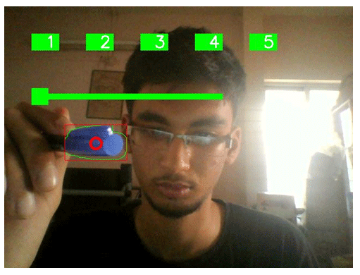
Fig. 1: Image showing Augmented Reality Interface designed through OpenCV
Things needed:

Fig. 2: Image showing logos of Arduino, python and OpenCV
· Opencv 2.4x
· Arduino Mega (or any other)
· Python 2.7x
· A blue object.
Circuit Description:
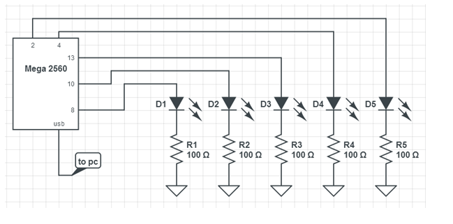
· Circuit is extremely simple. Connect pins 13,10,8,4,2 of Arduino to LEDs
· Connect a 100 ohm resistor between LED and ground.
· Have a common ground for all resistors.
Tracking Blue Object
1. Tracking blue object: After installing opencv and python, we can write a script to achieve following algorithm:
· Convert image to HSV colour space. Thresholding the image to achieve a mask that displays only blue objects.
· Selecting, stabilizing the contour and getting the centroid of the object.
· Applying morphological transformations.
· Using win32api library to give input for controlling cursor movements.
· Stabilizing the cursor movement for smooth flow.
![]()
Fig. 3: Image of Blue pen used as tracking device & Image of pattern captured by camera for blue pointer
Designing User Interface to Control Arduino
2. Designing User Interface to control Arduino/Circuit:
Program flow:

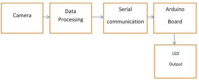
Fig. 4: Block Diagram of Arduino and OpenCV based Home Automation System
Python Script
· Code the python script to achieve toggle switch and push button like interface. 1, 2, 3 is push switch. 4, 5 is toggle switch.
· When the cursor co-ordinates correspond to switch co-ordinates serial communication occurs and the LEDs are toggled according.
· This can be extended to give any other required features.
· Push button: Serial communication occurs only when cursor is within the rectangle of the switch. Hence LED glows as long as this happens.
if (ix>150 and ix<200):
if(iy>50 and iy<80):
rect_col2=(0,0,255) # if within rectangle send char over ser ser.write(‘b’)
else:
rect_col2=(0,255,0)
· Toggle switch: Once the cursor is within the switch rectangle it turns on and remains in that state till the cursor again comes within the switch rectangle.
Here we need to check transition, suppose variable flag=0 if it is outside rectangle and 1 if within rectangle. pflag is the value of flag variable in previous loop. So if pflag=0 and flag=1 then send command over serial.
if (ix>350 and ix<400):
if(iy>50 and iy<80):
#print ‘got it4’ flag4=1
else:
flag4=0
if (pflag4==0)and(flag4==1):
print ‘****************************’ if (n4%2)==0:
rect_col4=RED
ser.write(‘d’)
if (n4%2)==1: rect_col4=GREEN ser.write(‘e’)
n4=n4+1
· Analog slider bar: Data is taken from the position of the rectangle and mapped to get value from 0-255. This value is then sent over serial.

Fig. 5: Screenshot of Augmented Reality Interface designed for Arduino based Home Automation System
Arduino Code
· Arduino code includes reading serial commands and filtering them accordingly
· However for analog value input the data is a char and may be a 1 or 2 or 3 digit number.
Thus we need to consider 3 cases:
Input char is like ‘h100’ or ‘h23’ (‘h’ is for selecting analog slider bar controlled LED and the rest is analog value)
if(c==’h’)
{
for(int i=2;i>=0;i–)
{
int temp=((int)Serial.read()) – 48; #reading the number delay(100);
ch[i]=temp;
}
if(ch[0]!=-49) #if it is 3 digit
{
for(int i=2;i>=0;i–)
{
ang+=ch[i]*pow(10,i);
}
}
else #if 2 digit
{
ang+=ch[1];
}
if((ch[0]==-49)&&(ch[1]==-49)) # if 1 digit number
{
ang=ch[2];
}
Circuit Diagrams
Filed Under: Electronic Projects


Questions related to this article?
👉Ask and discuss on Electro-Tech-Online.com and EDAboard.com forums.
Tell Us What You Think!!
You must be logged in to post a comment.