The DC motors come with voltage and RPM ratings. The RPM (Rounds Per Minute) rating indicates the maximum speed with which the motor can rotate. The speed of a DC motor varies with the voltage supplied to it. The motor rotates for the maximum speed when it gets the supply equal to its voltage rating. For supply voltages lower than their voltage rating, DC motors rotate at lower speeds. For example, a DC motor with 18V 200 RPM rating can rotate at maximum speed of 200 RPM when supply voltage to it is 18V. For supply voltage lower than 18V, it rotates at lower speeds.
The speed of a DC motor can be controlled by varying the supply voltage. The L293D is a common IC used to interface DC motors with the microcontrollers. The speed of DC motor can be controlled by switching supply voltage to the motor from the enable pin of the IC. When a DC motor gets continuous supply from the L293D IC, it rotates for the maximum speed. By altering the supply, the overall voltage supplied to the motor can be varied therefore varying the speed of the DC motor. The supply to the IC can be altered using Pulse Width Modulation (PWM) from the microcontroller. In this project, the speed of a DC motor is controlled using the same principle.
Additionally, the control to increase or decrease the speed of DC motor is regulated from a NEC IR Remote. The Volume Up button is used to signal for increasing the speed of the DC motor while Volume Down button is used to signal for decreasing the speed of the DC motor.
The controller board used in the project is Arduino UNO. The Arduino IDE is used to write the program code for decoding NEC signal and accordingly generate PWM output to control the DC motor. The program code is burnt to the board using AVR Dude.
COMPONENTS REQUIRED
1. Arduino UNO
2. DC motor
3. NEC IR remote
4. Motor driver IC-L293D
5. Connecting Wires

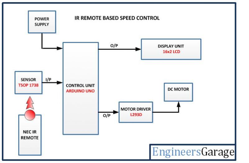
Fig. 1: Block Diagram of NEC IR Remote based DC Motor Speed Controller
CIRCUIT CONNECTIONS
The circuit is based on Arduino UNO. The different sections of the circuit will be interfaced with the Arduino board. The circuit will be assembled in the following sections – :
Power Supply – The power to the circuit will be supplied by 18V-24V battery. The Arduino board, LCD display and TSOP 1738 IR sensor need 5V supply while the L293D will need 12V DC supply. The supply from the battery will be regulated to 5V and 12V using 7805 and 7812 ICs. The pin 1 of both the voltage regulator ICs will be connected to the anode of the battery and pin 2 of both ICs will be connected to ground. The respective voltage outputs will be drawn from pin 3 of the respective voltage regulator ICs.
TSOP 1738 IR Sensor – The TSOP 1738 IR sensor will be used to receive the data from the NEC IR remote. The sensor has three terminals of which pin 1 will be connected to 5V VCC and pin 2 will be connected to the ground. The digital output from the sensor will be received from pin 3 which will be connected to the pin 11 of Arduino board.
16X2 LCD – The 16X2 LCD display will be used to display the increment or decrement of motor speed. It is connected to the Arduino board by connecting its data pins to pins 3 to 6 of the Arduino board. The RS and E pins of the LCD are connected to pins 13 and 12 of the Arduino UNO respectively. The RW pin of the LCD is grounded.

Fig. 2: Table listing circuit connections between Arduino Uno and Character LCD
The standard open-source library for interfacing LCD with Arduino UNO is used in the project. The library works as expected and needs no changes or modifications.
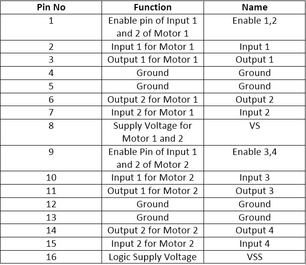
L293D DC Motor Driver IC – The L293D is the motor control driver IC. It has 16 pins with following pin configuration -:

Fig. 3: Table listing pin configuration of L293D Motor Driver IC
The DC motor controlled in the circuit will be connected between pins 11 and 14 of the IC.
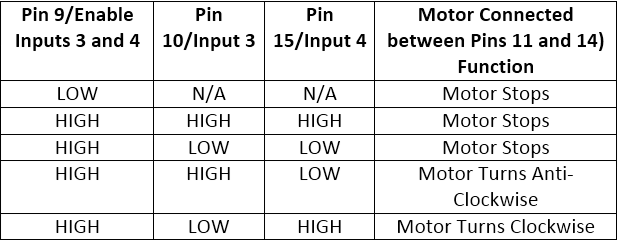
The L293D IC controls the DC Motors according to the following truth tables -:

Fig. 4: Truth Table of L293D Motor Driver IC

Fig. 5: Truth Table of L293D Motor Driver IC
The pin 10 of the L293D is grounded while pin 15 is connected to VCC, therefore the DC motor connected between pins 11 and 14 is configured to rotate clockwise.
The pin 16 (VSS) is connected to 5V DC and pin 8 (VS) is connected to 12V DC supply. The pins 12 and 13 are grounded. The pin 9 (enable pin for motor) is connected to the pin 9 of the Arduino board to receive PWM signal.
NEC IR remote – A regular NEC IR remote is used in the circuit. The Volume Up, Volume Down and Power buttons of the IR remote will be used for the following functions -:

Fig. 6: Table listing NEC IR Remote buttons and their respective functions for DC Motor Speed Control
HOW THE PROJECT WORKS
When the project is powered on, initial messages are flashed on the LCD display and the microcontroller is set ready to read IR keys decoded by the TSOP 1738 IR sensor. The PWM with duty cycle 78 percent is output to the enable pin of the L293D IC.
The NEC IR remote used in the project sends 28-bit long encoded IR keys. NEC IR remote uses a transmission protocol known as pulse distance encoding of the message bits, where each message packet is 562.5us in length and the 38KHz carrier frequency is about 26.3us in length. Logical “0” consists of burst pulses of 562.5us and followed by a 562.5us space. So the total time is 1.125ms while Logical “1” consists of burst pulses of 562.5us and followed by a 16875ms space. So the total time is 2.25ms. On pressing Volume Up, Volume Down and Power button following keys are transmitted by the remote control – :

Fig. 7: Table listing NEC IR Remote buttons and respective NEC signal encoding
The IR remote keys are read by the TSOP 1738 IR sensor and transmitted to the Arduino board. The Arduino has the program code to detect the IR key received and accordingly hardware PWM to the enable pin of the L293D IC.
When the Volume Up button is pressed on the IR remote, the IR key transmitted is 0x1FE609F. When the program code reads the stated key, it increases the duty cycle of the PWM output to the enable pin of L293D IC. At the same time, messages are flashed on LCD display to indicate that speed of the DC motor has been increased. On increasing the duty cycle of the PWM, the L293D IC is regulated to keep the voltage supply to the motor ON for longer period, therefore achieving higher rotational speed.
When the Volume Down button is pressed on the IR remote, the IR key transmitted is 0x1FE50AF. When the program code reads the stated key, it decreases the duty cycle of the PWM output to the enable pin of L293D IC. The messages showing the speed of DC motor has been decreased are flashed on the LCD display. On decreasing the duty cycle of the PWM, the L293D IC is regulated to keep the voltage supply to the motor ON for shorter period, therefore decreasing the rotational speed of the motor.
When Power button is pressed on the IR remote, the IR key transmitted is 0x1FE48B7. When the program code reads the stated key, it sets the duty cycle of the PWM output to the enable pin of L293D IC to 0 percent. Therefore the DC motor is stopped.
PROGRAMMING GUIDE
The program code will run on the Arduino board. In the program code, first the standard open-source libraries of Arduino for interfacing LCD and IR receiver are imported.
A variable is declared and assigned to pin 11 where output from the IR receiver is connected. An object of the IR receiver class is initialized and assigned to the variable. An object of LCD class is declared and is mapped to the Arduino pins where LCD is connected. A variable to hold the IR key is declared and pin 9 where PWM is output is assigned to variable named pwm. A variable is declared to hold the duty cycle value and is initialized to 200.
A setup() function is declared in which the baud rate for serial transmission of data to the LCD is set to 9600 bits per second using Serial.begin() function. The LCD is initialized using lcd.begin() function and microcontroller is set ready to receive IR keys using irrecv.enableIRIn() function. The PWM pin is set to digital output and PWM output with duty cycle 78% is output using AnalogWrite() function. Some initial messages are flashed on the LCD display indicating the purpose of the project.
The loop() function is called in which the received IR keys are detected using irrecv.decode() function. If the IR key received is 0x1FE609F corresponding to Volume Up button, the value in the variable holding duty cycle is increased and PWM output with increased duty cycle is passed to pin 9 using AnalogWrite() function. A message “Increasing Speed” is displayed on the LCD.
If the IR key received is 0x1FE50AF corresponding to Volume Down button, the value in the variable holding duty cycle is decreased and PWM output with decreased duty cycle is passed to pin 9 using AnalogWrite() function. A message “Decreasing Speed” is displayed on the LCD.
If the IR key received is 0x1FE48B7 corresponding to the Power button, the value in the variable holding duty cycle is set to 0 and PWM output with 0% duty cycle is passed to pin 9 using AnalogWrite() function.
By default, the controller is set to pass the current value in the variable holding duty cycle and PWM output with duty cycle according to current value is passed to pin 9 using AnalogWrite() function. In the end of the loop, the controller is configured to receive the next IR key by calling the irrecv.resume() function.
This ends the program code for DC motor speed control project using NEC IR Remote.
Project Source Code
###
#include <IRremote.h> #include <LiquidCrystal.h>//import the LCD library int RECV_PIN = 11; IRrecv irrecv(RECV_PIN); LiquidCrystal lcd(13, 12, 6, 5, 4, 3);// Pins used for RS,E,D4,D5,D6,D7 decode_results results; int pwm=9; int x=200; void setup() { //Serial.begin(9600); lcd.begin(16,2);//LCD 16x2 initialization irrecv.enableIRIn(); // Start the receiver pinMode(pwm, OUTPUT); analogWrite(pwm, x); lcd.setCursor(0,0); //Initially set the cursor position of LCD to 1st Columb 1st row. lcd.print("Engineers Garage");//After initialising print data lcd.setCursor(0,1); //Initially set the cursor position of LCD to 1st Columb 2nd row. lcd.print(" "); //print blank to clear all the data on LCD delay(3000); lcd.setCursor(0,0); lcd.print(" IR Based Speed "); lcd.setCursor(0,1); lcd.print("Control DC Motor"); delay(3000); } void loop() { if (irrecv.decode(&results)) { // IF VOLUME+ BUTTON IS PRESSED .... if(results.value==0x1FE609F){ if(x<1000){ x=x+60; delay(400); } lcd.setCursor(0,1); lcd.print("INCREASING SPEED"); delay(100); lcd.setCursor(0,1); lcd.print(" "); delay(100); } if (results.value==0x1FE50AF){ // IF VOLUME- BUTTON IS PRESSED .... if(x>0){ x=x-20; delay(400); } lcd.setCursor(0,0); lcd.print("DECREASING SPEED"); delay(100); lcd.setCursor(0,1); lcd.print(" "); delay(100); } if (results.value==0x1FE48B7){ analogWrite(pwm,0); } analogWrite(pwm,x); irrecv.resume(); // Receive the next value } }###
Circuit Diagrams
Filed Under: Electronic Projects


Questions related to this article?
👉Ask and discuss on EDAboard.com and Electro-Tech-Online.com forums.
Tell Us What You Think!!
You must be logged in to post a comment.