NOR Gate is created by applying NOT operation to an OR gate. Hence, the outputs of this gate are opposite to that of OR gate when the inputs are kept same. Shown below are the symbol and truth table for NOR gate.

Fig. 1 : Symbolic Representation Of Nor Gate
Input |
| Output |
A | B | Y |
0 | 0 | 1 |
0 | 1 | 0 |
1 | 0 | 0 |
1 | 1 | 0 |
Logic gate consists of three basic logic gates namely NOT, AND and OR. Each of them performs a different logic function. So we can derive logical function or any Boolean or logic expression by combination of these gate.
To understand the conversion we have to first understand the working of individual gate-
1.NOT Gate- This is the simplest form of a digital logic circuit . It is also called as inverter. It consist of only one input and one output and input can only be binary number it may be one or zero. NOT gate is a logic element whose output stage is always the complement of the input stage means when you supply logic 1 we will logic 0 and vice versa. Now how many stage are possible is calculated by 2n (where n is the number of input) means hear we have input equal to 1 so number of stage possible is 0 and 1 (21). Truth table of NOT gate is as follows-
|
Input(21) |
Output |
|
A |
NOT A |
|
0 |
1 |
|
1 |
0 |
2.AND Gate- It is logic circuit has two input and one output. The operation of gate is such that output of gate is binary 1 if and only if all input are binary 1. If any of the input is binary 0 we will receive output as binary 0. Truth table of AND gate are as follows-
Number of stage possible = 2n
=22 = 4
|
Input |
Output |
|
|
A |
B |
A.B |
|
0 |
0 |
0 |
|
0 |
1 |
0 |
|
1 |
0 |
0 |
|
1 |
1 |
1 |
3.OR Gate- Or gate is another basic logic gate like AND gate it as two input and one output. The operation of gate is such that output of gate is binary 1 if any of the input is binary low and we will receive logic zero only when both the inputs are low. Truth table of OR gate are as follows-
Number of stage possible = 2n
=22 = 4
|
Input |
Output |
|
|
A |
B |
A+B |
|
0 |
0 |
0 |
|
0 |
1 |
1 |
|
1 |
0 |
1 |
|
1 |
1 |
1 |
4.NOR Gate- The term NOR is a contraction of the expression NOT and OR gate. Therefore a NOR gate is an OR gate followed by the inverter. The operation of gate is such that output of gate is binary 1 if both the input is binary low and we will receive logic zero only when any of the inputs are high. Truth table and expression of NAND gate are as follows-
|
Input |
Output |
|
|
A |
B |
NOT (A OR B) |
|
0 |
0 |
1 |
|
0 |
1 |
0 |
|
1 |
0 |
0 |
|
1 |
1 |
0 |
For understanding the conversion, one should know about De Morgan’s theorem- It states that complement of sum is equal to the product of the complements.
NOT (A OR B)= NOT (A) AND NOT (B) —- EQ 1
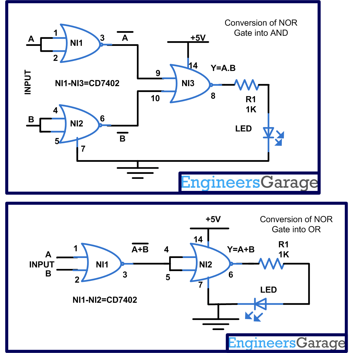
In the circuits,
We have used two NOR gate and short the input of each gate so we will get output as
= NOT (A) OR NOT(B)
Now it is again supplied to another NOR gate and we will get output as-
= NOT[(NOT) (A)] OR [(NOT) (B)]
= [NOT(NOT)(A)] AND[ NOT(NOT)(B)] (From EQ 1)
= A.B
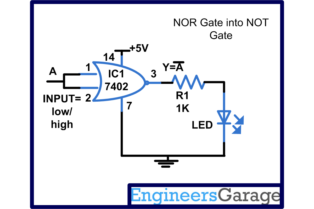
Circuit Diagrams
| Circuit-Diagram-For-Conversion-of-NOR-gate-to-Basic-gates |  |
| Circuit-Diagram-For-Conversion-of-NOR-gate-to-Basic-gates-2 |  |
Project Components
Filed Under: Electronic Projects


Questions related to this article?
👉Ask and discuss on EDAboard.com and Electro-Tech-Online.com forums.
Tell Us What You Think!!
You must be logged in to post a comment.