An attempt is made to derive 1024ppr (pulse per revolution) from 9000/18000/36000ppr, by designing an embedded circuit. A Feeder CNC machine has the rotary table acts as axis in milling mode and as spindle in turning mode. In order to operate in the axis mode, machine requires 9000/18000/36000ppr and to operation in the spindle mode requires 1024ppr. To achieve these required pulses for turning and milling process, HEIDENHAIN manufactured of position feed devices (Dual Encoders) having two encoders one for milling and another for turning. The main problem is that the manufacturer of the dual encoders stopped the production. Only single encoders are available in the market. So we have to attempt derive dual encoder from the single optical encoder. To solve the requirements of spindle mode of CNC machine using single optical encoder, a simple circuit is designed to obtain 1024ppr using pulse division method.
INTRODUCTION
In turning cum Milling CNC machines, the rotary table works as axis in milling mode and in turning mode, it will work as spindle. In the turning mode, the tool is fixed and the job is rotating, whereas in the milling mode, the tool is rotating and the job is fixed. For axis mode, CNC requires 9000/18000/36000ppr (pulses per revolution) pulses and for spindle mode, 1024ppr pulses. To achieve this HEIDENHAIN, the manufacturer of position feed devices, manufactured Dual Encoders, which will have two different encoders in single case.
Due to aging and other parameter 36000/18000ppr or 1024ppr may not functioning, which will in turn, increase the down time of such a critical machine. If Dual encoder is defective, the CNC turning cum milling machine will come to stand still condition, as Dual encoder are absolute. The main problem is that the manufacturer of the dual encoders stopped the production. Only single encoders are available in the market. So we have to derive dual encoder from the single encoder. Also the cost of the dual encoder is also very high. Achieving 1024ppr pulses from 18000/36000ppr pulses, by designing an embedded based electronic circuit, will solve requirements of CNC spindle application. Thereby, we can get Dual mode from a single Encoder.

Fig. 1: Block Diagram of Single to Dual Optical Encoding Converter
The output from the exe unit is such that, it is of 1, 80,000 PPR. We have to derive 1,024 PPR from this 1, 80, 000 PPR. To achieve this, we have many techniques. Among the available techniques, we adopted division method. This division method is carried out with help of edge detection. The important note is that, as the division is carried out on the incoming signal, the 90degree phase is not maintained. In order to maintain this, a separate technique is adopted, as we will see shortly. Soon after this process, 90degree maintenance must have to be verified. This is done with the help of 90degree verification unit as shown in the block diagram below. Once this process is over, it is to be decided whether forward or reverse process to be carried out. This is done with the help of forward & reverse verification unit.
EDGE DETECTION
Achieving 1024 PPR pulses from 18000/36000PPR pulses from the encoder output is carried out with help of simple digital logic circuit called edge detector. This logic is obtained with the help of two OR gates, AND gate and a NOT gate to detect the edge of each pulses to carry out the division process to meet our requirement. Our edge detection circuit designed here for the purpose of detecting falling edges, this edge is used as the reference for the division. This is carried out with the help of the circuit shown below and its truth table to describe its process.

Fig. 2: Circuit Diagram of Edge Detector
The complementary version of output is feedback to OR gate (OR1) along with the incoming input signal. The output of the OR1 gate is the detected edge. For example, let us assume that both the input and output are same, as said already. For the first transition during the LOW state of input & output, the EDGE OUTPUT is LOW. During the second transition of the LOW state and HIGH state of INPUT & output, the EDGE OUTPUT is HIGH. That small transition shows the detection of the edge. Thus, the transition is used to find the edge with the help of the above shown circuit. The graph showing the input & edge circuit output (output of the OR gate OR1) is shown below.

Fig. 3: Graph showing Edge Detection

Fig. 4: Truth Table for Edge Detection
Truth table for Edge detection with graphical representation
Edge Counting and Division
EDGE COUNTING AND DIVISION
Our main of detecting edge is to convert the encoder output to meet out division processes. Once the edge has been detected this edge has to be count with respect to edge to perform division, for example in order to perform division by two every second edge from the edge detection circuit must be taken in to account for our division processes. Pulse from axis mode is of the range of 1,80,000ppr can be reduced to 90,000ppr using edge detection and counting.

Fig. 5: Block Diagram of Edge Counter

Fig. 6: Graph showing Edge Counting
Division of a wave
1,80,000ppr – pulse obtained from Axis mode from encoder.
1,80,000/2 – division by two process applied after edge detection and counting to meet 90,000ppr
Similarly division processes is performed to meet our spindle mode ppr from single encoder, 1,80,000 ppr pulse is divided by 176 with respect to edges to meet 1022.727ppr pulse for spindle mode.
90degree PHASE SHIFT BETWEEN PULSES
Main aspect in our project is that, at all the stages, 90 degree phase shift must have to be maintained. But once the signal is divided by some integer, the 90 degree phase shift is not maintained, which happened due to division process.

Fig. 7: Graph showing not maintained 90 Degree Phase Shift
This 90 degree phase is usually maintained to manage forward and reverse movement of CNC machine, if this phase shift is not maintained between pulses it loses it accuracy.
To maintain this 90degree phase shift between two encoder signals, the following procedure is followed:
• Get the divided output.
• Complement the divided output.
• Then again divide the two signals (divided & its complementary counterpart).
• Check 90degree phase shift.

Fig. 8: Graph showing maintained 90 Degree Phase Shift
KILLING & ADDING OF PULSES
In order to obtain the required number of pulses to the CNC machine to operate in the turning mode, we divide the 1, 80, 000 PPR by 176. So approximately we are 1022.727272 PPR for the machine to operate in the turning mode. But this is only an approximation. The exact 1024 PPR is achieved using pulse killing & adding.
1, 80, 000 / 180 = 1000 + 24 = 1024 PPR (adding of pulses)
1, 80, 000 / 120 = 1500 – 476 = 1024 PPR (killing of pulses)
IMPLEMENTATION AND RESULTS
The above techniques are programmed into a microcontroller for efficient process, circuit simplicity and to make our encoder cost effective in industrial application. Our circuit consists of an encoder section, a microcontroller and a comparator. After fusing of above techniques in to a microcontroller our circuit is tested to meet out design requirement.
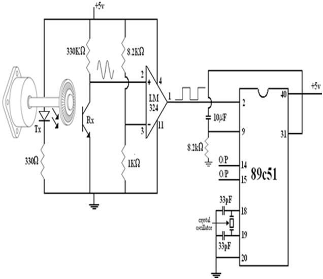
The circuit shown in Circuit Diagram Tab 1 and technique and its results are tested with a prototype model.

Fig. 9: Prototype of Single to Dual Optical Encoding Converter

Fig. 10: Image of output from Single to Dual Optical Encoding Converter observed on CRO
CONCLUSION
Single encoder was designed in suitable manner to work both in milling and turning mode, 1, 80, 000 PPR from the EXE unit was converted into to 1024 PPR using our division techniques. 90 degree phase shift between two signals was obtained using digital D flip-flop logic, using these techniques we get only 1022.76 PPR. CNC machine normally operates with 2 per cent of error but we get only 0.2 percent errors so it doesn’t affect its normal milling operation. When we come to accuracy it has some drawback in order to reduce this drawback we further making our 1022.76 PPR to 1024 PPR using our killing and adding of pulse techniques. Using this above techniques high accuracy was achieved. This embedded design circuit helps in remodeling CNC to work at lowest cost, high accuracy as per the HEIDENHEIN dual encoder was achieved in a short period of time.
Circuit Diagrams
Filed Under: Electronic Projects

Questions related to this article?
👉Ask and discuss on Electro-Tech-Online.com and EDAboard.com forums.
Tell Us What You Think!!
You must be logged in to post a comment.