This is a simple and basic tutorial for newbies on how to display a counting pattern on led’s. Its going to be a simple binary counting on led’s. Recall binary numbers(00=0, 01=1, 10=2, 11=3 and goes on). Led’s will lit up in binary order. Led’s blinking pattern will be in binary form. Led’s will be connected to port-1 of 8051 microcontroller. I am going to make a 4-bit and 8-bit binary counter with 8051 microcontroller and led’s. 4 bit binary counter can count from 0 to 15 and 8-bit counter can count from 0 to 255.
8051 microcontroller 4-bit led binary counter
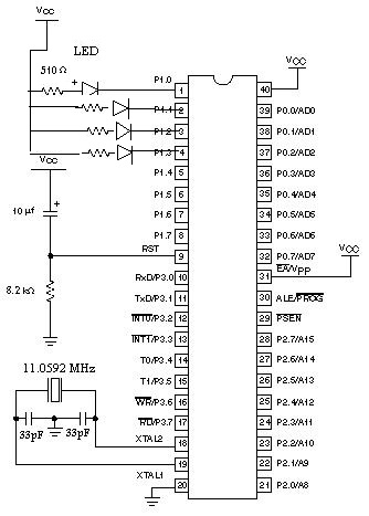
First i am going to make a 4-bit counter. For 4-bit counter we only need four led’s. Since a 4-bit counter maximum range of count is 15(1111 in binary and F in hexadecimal). I am using 89c52 microcontroller in the project.
You can use any other of 8051 series microcontrollers like 89c51, 89s51, 89s52 etc for this project. A slight change in code header file is required if you switch from 8051 to 8052 microcontroller. For 89c51 and 89s51 header file is reg51.h. But for 89c52 and 89s52 header file is reg52.h. So please be sure first which microcontroller you are using in your project and include the correct header file i code. This header file is only to be included if you are using keil as software to program your microcontroller. I am using keil u-vision3 for this project.
8051 microcontroller Led’s Binary counter – code
Code of the project is very easy, if you already have some basic knowledge of 89c51 microcontroller programming in keil ide and its code syntax. I used only two functions delay() and main() in code. Main is the main function which we use in our every microcontroller/software project. Delay function is used for giving delays in the execution of code statements. The while() loop in the main function is used to continuously run the program(counter).
The statement P1=0x01 is making port#1 pin#0 high. The statement
P1=0x01 is in hexadecimal form. In statement 0x means that the number is in hexadecimal from and the number comes right after 0x which in our case is 01. 01 in binary is equal to 01=00000001.After the
P1=0x01 statement comes 02=00000010 03=00000011 04=0000100 05=00000101 06=00000110 07=00000111 08=00001000 09=00001001 0A=00001010 0B=00001011 0C=00001100 0D=00001101 0E=00001110 0F=00001111. These bits are continuously being written to the port-1 pins with some delay in each statement. Since led’s are connected as output to port-1 the binary pattern will appear on led’s This logic makes them on and off and it seams to be counter running on them. Project circuit diagram is below.I am sending values in hexadecimal form to port-1 of 89c52 microcontroller in the above code. You an also send them in decimal form, to do so i write another program given below. There is one more way to carry out the task. Access port-1 pins individually by first declaring them sbit and then use them for led on and off. This is also an easy method but the code becomes too lengthy. Delay function is used to generate an arbitrary delay to pause the led count for some time for viewing the led output clearly. For loop is counting from 0 to 15 and count variable is updated every time. P1=count statement displays the counter value on the led’s connected to port-1.
4-bit Binary counter above same code in decimal form
8-bit binary counter on led’s with 8051 microcontroller
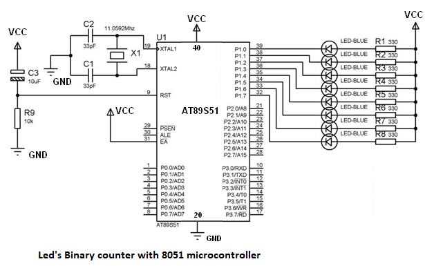
Eight bit counter is same like 4 bit only we need some extra statements in it. We are using four led’s in four bit counter now for 8-bit counter we have to use eight led’s. Just connect four more led’s to port 1 in the same way we connected above
The code for 8-bit counter is below only the change is in count variable because 8-bit counter can count up to 255. Now the for loop runs from 0 to 255 and statement P1=count outputs the counter value on the led’s connected at output.
Filed Under: 8051 Microcontroller., Microcontroller Projects


Questions related to this article?
👉Ask and discuss on EDAboard.com and Electro-Tech-Online.com forums.
Tell Us What You Think!!
You must be logged in to post a comment.