This project is going to guide you through making your very own light level detector, using cheap components and also providing compensation in the form of artificial light whenever the ambient light level in the room is low. Additionally, sensitivity adjustment can also be added for more precise systems.The sensor system can be used for a variety of applications such as an automatic stabilizer for light levels at home or at work, or you can just make one as a fun hobby or for a project. For this project reader need knowledge about how to start with arduino
WORKING PRINCIPLE
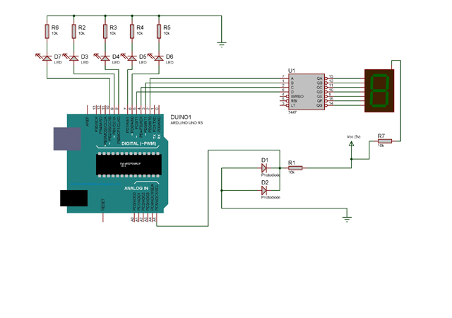
· The circuit measures the surrounding light using the photodiodes.
· Two photodiodes are connected in parallel for optimum performance.
· Anode is connected to the resistor and also to the analog input pin of the arduino board while the cathode is connected to the power supply.
· This analog signal is processed by the inbuilt ADC of the arduino board.
· The processed signal is then calibrated to form data which maps to a suitable range.
· The data is then fed in BCD form to the BCD to Seven segment (IC7447).
· The IC converts binary data and directly determines the appropriate segments to show the desired output.
· Simultaneously the arduino also switches on a number of led’s. this number is based on the measured value of surrounding light.
· The sensitivity of the instrument can be varied by changing the value of resistance in series with the photodiode or by connecting more photodiodes in parallel.
· Alternatively, if you wish to dynamically adjust the sensitivity, a 10k or 50k potentiometer can be connected in place of the resistor in series with the photodiodes.

Guidelines & Code Algorithm
PROCEDURE AND GUIDELINES
1) Gather the various components mentioned in the ‘components’ section. You can either use a breadboard to construct the circuit or for a more permanent model, a perf board can be used ( provided you have the adequate soldering skills).
2) Connect female jumper wires to the arduino so they can be detached easily for any modifications.
3) Connect the wires to the relevant pins of the IC. For soldered connections, an IC stand must be used, otherwise the IC could undergo heat damage.
4)Place the seven segment display close to the IC as it will make connections easier and save wire.
5) The photodiodes should be connected in reverse bias ( the longer of the two leads from the photodiode should be connected to ground).
6) Two or three photodiodes are connected in parallel for better accuracy. If only one is used, any change in direction of the incoming light will drastically change the reading. Use of multiple photodiodes for measurement will make the system more independent of the direction of incoming light and hence will give a more accurate reading for the intensity.
7) The photodiodes should be placed facing vertically upwards.
8) Connect the resistor connected to the photodiodes to a 5v supply. If you are using arduino, the power supply can be found on the board itself. If you are using another microcontroller, a 5v or 6v battery can be used.
9) Connect the leds to the appropriate pins on the arduino. The values of the resistors connected in series with the leds can be reduced in case the leds are too dim or not lighting at all.
10) IC 7447 can be tested by grounding pin 3 of the IC. It is recommended to test the IC before making soldered connections to the 7 segment display.
11) The anode of the CA 7 segment display can also be connected to the 5v power supply in series with a resistor.
12) The arduino is connected to the PC using an A-B USB cable.
13) Software used is open source and available on the arduino website.
14) The code is written in C language.
CODE ALGORITHM
a) The pins connected to the leds and IC7447 are configured as output pins, and the analog pin A0 is configured as an input pin.
b) Three continuous readings are taken from A0 at 1ms delay. The highest of the 3 readings is taken as the true reading (since the photodiodes are highly directional, so a 0 reading is not uncommon).
c) The absolute value of the reading is divided by 40, which gives the relative reading (can be divided by a lesser number if the sensitivity is to be increased).
d) Based on the value of the relative reading, the binary data is given to the pins connected to IC7447 and the pins connected to the leds are switched on or off. For example, if the relative reading is 5, 0101(5 in binary) binary data is given to the IC pins, and the amount of leds switched on is 2.
e) The process is repeated to give continuous readings.

Project Source Code
###
void setup(){Serial.begin(9600);pinMode(2,OUTPUT);pinMode(3,OUTPUT);pinMode(4,OUTPUT);pinMode(5,OUTPUT);pinMode(6,OUTPUT);pinMode(7,OUTPUT);pinMode(8,OUTPUT);pinMode(9,OUTPUT);pinMode(10,OUTPUT);}int takereading(){int r1=analogRead(A5);delay(1);int r2=analogRead(A5);delay(1);int r3=analogRead(A5);delay(1);int rr;if(r1>r2&&r1>r3)rr=r1;else if(r2>r1&&r2>r3)rr=r2;elserr=r3;return rr;}void loop(){int reading=takereading();int value=reading/40;Serial.println(value);if(value==0){digitalWrite(2,LOW);digitalWrite(3,LOW);digitalWrite(4,LOW);digitalWrite(5,LOW);digitalWrite(6,HIGH);digitalWrite(7,HIGH);digitalWrite(8,HIGH);digitalWrite(9,HIGH);digitalWrite(10,HIGH);}else if(value==1){digitalWrite(2,HIGH);digitalWrite(3,LOW);digitalWrite(4,LOW);digitalWrite(5,LOW);digitalWrite(6,HIGH);digitalWrite(7,HIGH);digitalWrite(8,HIGH);digitalWrite(9,HIGH);digitalWrite(10,LOW);}else if(value==2){digitalWrite(2,LOW);digitalWrite(3,HIGH);digitalWrite(4,LOW);digitalWrite(5,LOW);digitalWrite(6,HIGH);digitalWrite(7,HIGH);digitalWrite(8,HIGH);digitalWrite(9,HIGH);digitalWrite(10,LOW);}else if(value==3){digitalWrite(2,HIGH);digitalWrite(3,HIGH);digitalWrite(4,LOW);digitalWrite(5,LOW);digitalWrite(6,HIGH);digitalWrite(7,HIGH);digitalWrite(8,HIGH);digitalWrite(9,LOW);digitalWrite(10,LOW);}else if(value==4){digitalWrite(2,LOW);digitalWrite(3,LOW);digitalWrite(4,HIGH);digitalWrite(5,LOW);digitalWrite(6,HIGH);digitalWrite(7,HIGH);digitalWrite(8,LOW);digitalWrite(9,LOW);digitalWrite(10,LOW);}else if(value==5){digitalWrite(2,HIGH);digitalWrite(3,LOW);digitalWrite(4,HIGH);digitalWrite(5,LOW);digitalWrite(6,HIGH);digitalWrite(7,HIGH);digitalWrite(8,LOW);digitalWrite(9,LOW);digitalWrite(10,LOW);}else if(value==6){digitalWrite(2,LOW);digitalWrite(3,HIGH);digitalWrite(4,HIGH);digitalWrite(5,LOW);digitalWrite(6,HIGH);digitalWrite(7,LOW);digitalWrite(8,LOW);digitalWrite(9,LOW);digitalWrite(10,LOW);}else if(value==7){digitalWrite(2,HIGH);digitalWrite(3,HIGH);digitalWrite(4,HIGH);digitalWrite(5,LOW);digitalWrite(6,HIGH);digitalWrite(7,LOW);digitalWrite(8,LOW);digitalWrite(9,LOW);digitalWrite(10,LOW);}else if(value==8){digitalWrite(2,LOW);digitalWrite(3,LOW);digitalWrite(4,LOW);digitalWrite(5,HIGH);digitalWrite(6,LOW);digitalWrite(7,LOW);digitalWrite(8,LOW);digitalWrite(9,LOW);digitalWrite(10,LOW);}else{digitalWrite(2,HIGH);digitalWrite(3,LOW);digitalWrite(4,LOW);digitalWrite(5,HIGH);digitalWrite(6,LOW );digitalWrite(7,LOW);digitalWrite(8,LOW);digitalWrite(9,LOW);digitalWrite(10,LOW);}delay(100);}###
Circuit Diagrams
Filed Under: Electronic Projects

Questions related to this article?
👉Ask and discuss on EDAboard.com and Electro-Tech-Online.com forums.
Tell Us What You Think!!
You must be logged in to post a comment.