Gone are those unsafe days when people used smartphone or listen to headphones for navigation while cycling as the latest DIY project of Adafruit is a “smart helmet”, which navigates the user to where they want to go and even displays a light show.
Although the helmet is kind of tedious because users have to manually enter in coordinates and it requires well-versed experience to change paths while travelling. Further, it let the user know where to go through a series of lights and flashes. The helmet is based on the Adaruit Flora which is essentially an Adafruits wearable technology platform that form the basis behind most of their wearable technology. You can read about this technology on their website. This do it yourself project can be tried at home, if you have better knowledge of coding and programming. The hardware section doesn’t require much expertise but gathering those product could be a hectic task.
Equipment needed
To carry this project, the main ingredients are Carrera foldable helmet, NeoPixel strip of about 1.5m, FLORA main board, FLORA LSM303 accelerometer/compass, FLORA Ultimate GPS and Rechargeable lithium polymer battery and charger. One can also get coincell battery and holder but it is optional to improve GPS fix time along with Needle, scissor and clear thread
Hardware compilation
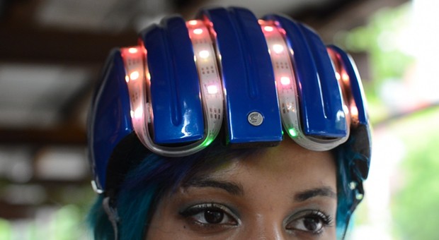
A long piece of NeoPixel strip is wrapped throughout the grooves in the helmet. The strip is shifted so that four LEDs are visible to the rider in the front brim. With a needle and clear thread, LED strip to the nylon webbing is tacked in the grooves of the helmet. But before strip is cut to the length of the opposite back edge. Then affix the FLORA main board to the back head using a needle and more clear thread. Bracing of the helmet through two unused pins is followed by stripping and tinning three wires and then soldering them to the input side of the LED strip.
The wiring program is perfectly described with diagrams on their website. Taking clue from it, wires are cut to length, strip and solder to VBATT, D6, and GND. After soldering small flexible wires to accelerometer/compass module, a small piece of Sugru is applied to cover the back of the module. This process of soldering described above is repeated with the GPS module, connecting corresponding to TX/RX pads to FLORA. Wiring describes that TX goes to RX and RX goes to TX.
Sugru used on the cover insulates the back of the GPS module from the LSM303 and FLORA main board provides a semi-permanent sticky situation. The silicone could be used but it is not quite an adhesive, though it will remain affixed unless choose to carefully peel it off. The lithium polymer battery slides is used behind the elastic of the head brace.
The citi bike helmet Arduino sketch, it’s wiring, coding and programming are exclusively present on the Adafruit site. Refer the website to gather all the information and make your project alive. All the best.
Filed Under: Reviews

Questions related to this article?
👉Ask and discuss on EDAboard.com and Electro-Tech-Online.com forums.
Tell Us What You Think!!
You must be logged in to post a comment.