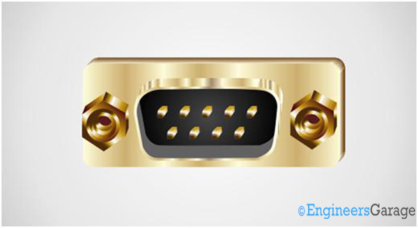
D connectors are common electrical connectors especially found in the communication ports of the personal computer. The name is due to its ‘D’ shape itself. The D connector has two or more parallel rows of contacts surrounded by a ‘D’ shaped metal frame. The polarization is automatically achieved in this connector due to this ‘D’ shape. The D connectors were designed by the ITT Cannon in 1952. The D connectors have both male and female connectors and the pin numbers are available from 9 pin to 25 pin contacts.

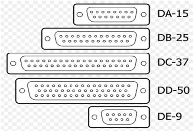
The specifications of the D-standard connectors are defined by international standard, IEC 60807-3 / DIN 41652. Four different standard connectors are defined under this IEC standard. These connectors primarily differ from each other by their shell size and number of pins. They are named as DA, DB, DC, DD and DE connectors followed by their number of pins. For example the 15 pin standard A connector is named DA-15, the 25 pin standard B connector is named DB-25, the 37 pin C standard connector is named DC-37, the 50 pin D standard connector is named DD-50 and the recently introduced 9 pin E standard connector as DE-9 connector. Many manufactures refer the DE-9 connector as DB-9 since it came as a replacement for the DB-25 connector of the computers RS232 port.
The drawing of different D-standard connectors is shown in the following image.

Fig. 2: Image showing standard D connectors
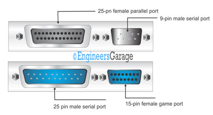
Most of these connectors are found as the peripheral connectors of PC. In the following image you can find a few D-standard connectors mounted on a PC cabinet.

Fig. 3: Image showing D connectors mounted on a PC cabinet
The D connectors which do not follow the above discussed standard are also available like DE15 connectors usually found in VGA cables and High Density (HD) connectors like DB26HD, DB44HD, DB62HD, and DB78HD connectors etc. The D connectors are available with a maximum current rating of 40A and maximum voltage ratings up to 13,500 V.
Now let us go through the common applications and pin-out of some of the D-standard connectors.
DA-15 and DA-25 Connector
DA-15
The DA-15 pin is a 15 pin D-standard connector commonly used as game port of the computer. The game boards and joysticks are available which can be attached with this connector. The female connector is mounted on the PC cabinet and the male connector is found in the gaming device. The pin position of a DA-15 male connector is shown in the following figure.

Fig. 4: Image of DA-15 connector
The pin-out of the 15 pin DA-15 connector for gaming device
PIN 1 ——————-+5V DC
PIN 2 ——————-BUTTON 1
PIN 3 ——————-X AXIS JOYSTICK 1
PIN 4 ——————-GROUND BUTTON 1
PIN 5 ——————-GROUND BUTTON 2
PIN 6 ——————-Y AXIS JOYSTICK 1
PIN 7 ——————-BUTTON 2
PIN 8 ——————-+5V DC
PIN 9 ——————-+5V DC
PIN 10 ——————BUTTON 4
PIN 11 ——————X AXIS JOYSTICK 2
PIN 12 ——————GROUND BUTTON 3 & 4
PIN 13 ——————Y AXIS JOYSTICK 2
PIN 14 ——————BUTTON 3
PIN 15 ——————+5V DC
DB-25
The DB-25 pin is a 25 pin D-standard connector commonly used in applications like RS-232 serial port, parallel port, parallel printer connector, multi-channel analog audio and AES digital audio etc. In PCs Female DB-25 connectors are used in parallel port and male DB-25 connectors are used in serial ports. The pin position of a DB-25 male connector is shown in the following figure.

Fig. 5: Image of DB-25 connector
The pin-out of the 25 pin DB-25 connector for parallel port
PIN 1 ——————-STROBE
PIN 2 ——————-DATA 0
PIN 3 ——————- DATA 1
PIN 4 ——————- DATA 2
PIN 5 ——————- DATA 3
PIN 6 ——————- DATA 4
PIN 7 ——————- DATA 5
PIN 8 ——————- DATA 6
PIN 9 ——————- DATA 7
PIN 10 ——————ACK
PIN 11 ——————BUSY
PIN 12 ——————PAPER OUT
PIN 13 ——————SELECT
PIN 14 ——————LINE FEED
PIN 15 ——————ERROR
PIN 16 —————— RESET
PIN 17 ——————SELECT PRINTER
PIN 18 ——————GROUND
PIN 19 ——————GROUND
PIN 20 ——————GROUND
PIN 21 ——————GROUND
PIN 22 ——————GROUND
PIN 23 ——————GROUND
PIN 24 ——————GROUND
PIN 25 ——————GROUND
The pin-out of the 25 pin DB-25 connector for serial port
PIN 1 ——————-PROTECTIVE GROUND
PIN 2 ——————-TXD
PIN 3 ——————- RXD
PIN 4 ——————- RTS
PIN 5 ——————- CTS
PIN 6 ——————- DSR
PIN 7 ——————- GROUND
PIN 8 ——————- DCD
PIN 9 ——————- NOT CONNECTED
PIN 10 —————— NOT CONNECTED
PIN 11 —————— NOT CONNECTED
PIN 12 —————— NOT CONNECTED
PIN 13 —————— NOT CONNECTED
PIN 14 —————— NOT CONNECTED
PIN 15 —————— NOT CONNECTED
PIN 16 —————— NOT CONNECTED
PIN 17 —————— NOT CONNECTED
PIN 18 —————— NOT CONNECTED
PIN 19 —————— NOT CONNECTED
PIN 20 ——————DTR
PIN 21 —————— NOT CONNECTED
PIN 22 ——————RI
PIN 23 —————— NOT CONNECTED
PIN 24 —————— NOT CONNECTED
PIN 25 —————— NOT CONNECTED
DE-9 and DE-15 Connector
DE-9
This 9 pin DE-9 standard D connector is mostly referred to as DB-9 connector, but it is totally different in shell size and pin number of DB standard connector. They are applied as a replacement for the large DB-25 serial port in modern PCs. They are also used in token ring network, computer network, CAN etc. The pin position of a DE-9 male connector is shown in the following figure.

The pin-out of the 9 pin DE-9 connector for serial port
PIN 1 ——————- DCD
PIN 2 ——————- RXD
PIN 3 ——————- TXD
PIN 4 ——————- DTR
PIN 5 ——————- GROUND
PIN 6 ——————- DSR
PIN 7 ——————- RTS
PIN 8 ——————- CTS
PIN 9 ——————- RI
Pin description:
DTR: Data Terminal Ready, Indicates presence of DTE to DCE
DCD: Data Carrier Detect, DCE is connected to the telephone line
DSR: Data Set Ready, DCE is ready to receive commands or data
RI: Ring Indicator, DCE has detected an incoming ring signal on the telephone line
RTS: Request To Send DTE requests the DCE prepare to receive data
CTS: Clear To Send, Indicates DCE is ready to accept data
TXD: Transmitted Data, Carries data from DTE to DCE
RXD: Received Data, Carries data from DCE to DTE
DE-15
This 15 pin connector is not actually a DE standard connector since its shell size and pin numbers are different from that of a DE standard connector. This connector is widely used as a connector for the VGA port of PC, monitors etc. The pin position of a DE-15 male connector is shown in the following figure.

Fig. 7: Image of DE-15 connector
The pin-out of the 15 pin DE-15 connector for VGA port
PIN 1 ——————- RED
PIN 2 ——————- GREEN
PIN 3 ——————- BLUE
PIN 4 ——————- NOT USED
PIN 5 ——————- GROUND
PIN 6 ——————- RED GROUND
PIN 7 ——————- BLUE GROUND
PIN 8 ——————- GREEN GROUND
PIN 9 ——————- POSITIVE
PIN 10 —————— GROUND
PIN 11 —————— ID BIT 0
PIN 12 —————— DATA
PIN 13 —————— HORIZ SYNC
PIN 14 —————— VERT SYNC
PIN 15 —————— DATA
Sample specification:
Insulation Resistance ——————– 1,000M? min.
Dielectric Strenght ———————– 1,000 V AC min. for 1 minute
Voltage Rating —————————- 300V DC
Withstanding Voltage ——————- 500V AC for 1 Minute
Contact Resistance ———————– 20m? max.
Current Rating —————————– 1.5A
Summary
{C}{C}{C}{C}{C}· {C}{C}{C}{C}{C}The name D connector is due to the ‘D’ shaped metal frame surrounding the contact pins
{C}{C}{C}{C}{C}· {C}{C}{C}{C}{C}The D-shape automatically makes it polarized connector
{C}{C}{C}{C}{C}· {C}{C}{C}{C}{C}The basic D-standard connectors are DA-15, DB-25, DC-37, DD-50 and DE-9 connectors.
{C}{C}{C}{C}{C}· {C}{C}{C}{C}{C}DA-15 is used for gaming devices, DB-25 is used as parallel and serial port of PC, DE-9 is used as serial port in PC.
{C}{C}{C}{C}{C}· {C}{C}{C}{C}{C}DE-9 connector when used as serial port in PC is otherwise referred to as DB-9 since it replaces large the DB-25 serial connector.
Filed Under: Tutorials


Questions related to this article?
👉Ask and discuss on EDAboard.com and Electro-Tech-Online.com forums.
Tell Us What You Think!!
You must be logged in to post a comment.