Here is very useful application that controls the number of rotation of 12 V DC gear motor with very low RPM (1,2,3,5 or 10 etc). Its a remote control application in which you can program and set the number of rotations of motor for different buttons. There are four different buttons for which motor rotates different number of rotations. Another four buttons are given to change the number of rotations for above four buttons. The remote can be IR or RF.
You may find lots of applications of this project in robotics, CNC machines, manufacturing industries etc. Here are some of the examples
1) In any PCB cutting or PVC pipe cutting CNC machine (or any other automatic cutting machine) first the linear dimensions are calibrated in terms of number of rotations (e.g. 5 rotations = 1 CM), then by adjusting the number of rotations as per required dimension one can easily move the cutting tool to that distance (e.g. for 1 meter 500 rotations).
2) In robotic arm application, if the arm has to move to a specific position then first its movement can be calibrated in terms of number of rotations of motor. Afterwards once we program and set the number of rotations for a button, the arm will always move to that position when that button is pressed.
3) In conveyor belt control system, the object has to be moved to a specific distance for next process after current process is over. this distance is fixed, so if this linear distance is calibrated in terms of motor rotations then the object can be moved to exact distance by controlling number of rotations of motor
Thus i can give number of such applications and examples of this project where it can be used. Its very small but indeed a very useful projects for above types of applications. so now let us see how it is done…..
let us start with understanding block diagram of the system
System Block Diagram: –
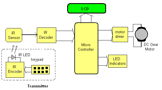
the system is made up of two sections. (1) Transmitter section- remote control (2) controlling section
Transmitter section is a single chip remote control made up of Encoder chip. it requires no other components. its a specially programmed micro controller that is used especially for designing IR or RF remote controls. it gives 8 channel interface so we can perform 8 different functions.
Controlling section includes IR sensor, IR decoder, micro controller, LCD and motor driver chip
IR Sensor: – it detects IR signal transmitted by IR led of remote control and gives this detected signal to IR decoder
IR decoder: – this is used in pair with IR Encoder chip. it is also specially programmed micro controller for designing IR or RF remote control. it gives 8 outputs as Hi / Low that are given to micro controller
micro controller: – it performs following tasks
· controls the rotations of motor
· displays number of rotations of motor for each buttons on LCD
· Gives different indications on LEDs like remote sensor, motor is running, setting process is OB etc…
LCD: – it displays different parameters and messages on screen. it displays set number of rotations for each buttons. it displays messages like “set process over” “press button 1 – 4” etc.
Motor driver: – it amplifies the output of micro controller and provides sufficient current to the motor to rotate.
LED indicators: – it indicates key press form remote control; motor is running, set process in ON etc on different color LEDs
Circuit Diagram & Working operation
Circuit Diagram: –
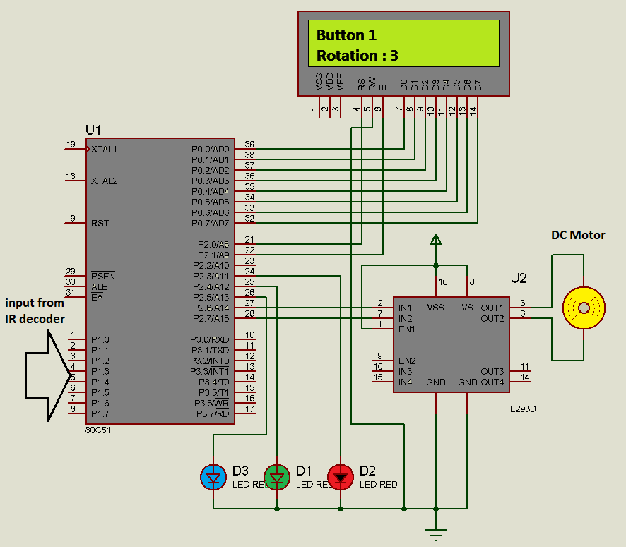
The circuit diagram tab 1 figure shows schematic diagram of the project. it is not full and complete circuit but just shows the possible arrangement of how the various chips are interfaced with micro controller 8051. It shows majority of connections. Encoder – Decoder chips connections are not shown here.
Connections: – all 8 outputs from decoder chips are connected with port P1. The data pins of LCD D0-D7 are connected with port P0. Two control signals RS and En are connected with P2.0 and P2.1. RW pin (read/write) is connected to ground. Port pins P2.6 and P2.7 drives 12 V DC gear motor through H-bridge motor driver chip L293D. Both pins are connected to inputs of L293D and output drives the motor. Three LEDs Red, Green and Blue are connected with port pins P2.3, P2.4 and P2.5 as shown. Crystal and reset circuit connections for micro controller are not shown here. 12 V power supply is used for DC motor and L293D chip.
Working and operation:-
There are 8 buttons in remote control that performs following actions.
|
sr no |
remote button |
action / function |
|
1 |
button 1 |
rotates motor till set number of rotations are complete |
|
2 |
button 2 |
rotates motor till set number of rotations are complete |
|
3 |
button 3 |
rotates motor till set number of rotations are complete |
|
4 |
button 4 |
rotates motor till set number of rotations are complete |
|
5 |
button 5 |
starts process of setting number of rotations for first 4 buttons |
|
6 |
button 6 |
increase number of rotation by 1 for button |
|
7 |
button 7 |
decrease number of rotation by 1 for button |
|
8 |
button 8 |
enter |
From above table it is clear that first four buttons are to rotate motor for different number of rotations and rest four buttons are for setting number of rotations for these buttons. initially, for first four buttons the number of rotations is set as 1. to change the number of rotations, one has to press button 5. Then he has to enter the number of rotations for all four buttons one by one. Setting of number of rotation can be done using increment / decrement button (button 6, 7). The complete step by step operation is as follows
- Initially do not press button 1 to 4. first to set the number of rotations, press button 5
- the message displayed “set num of rotation for button 1”
- now with the help of inc / dec button set desire number of rotations
- Press enter. immediately message is displayed “set num of rotations for button 2”
- repeat the steps for all four button
- After pressing enter when number of rotations for button 4 are set, the set process is over.
- It is displayed as “set process is over press button 1 – 4”.
- That means now as you press any of the button from 1 to 4 the LCD displays “button 1”, “rotations:3” and motor rotates for 3 complete rotations.
In this project I have used IR LED and IR Sensor as transmitter and receiver along with Enc-Dec chips for making remote control. But as I said in introduction that remote control can be RF also and for that we have to just replace the IR LED and sensor with ASK transmitter and receiver along with few modifications in Enc – Dec chips circuits. so that will provide all the benefits of RF remote controls like more range (up to 100 meter) no line of sight required etc.
Video
Video
Project Source Code
###
#include <reg51.h>#include <string.h>sbit rs = P3^2; // declare P2.7 as rs pinsbit en = P3^3; // declare p2.5 as enable pinsbit op1 = P3^6;sbit op2 = P3^7;sbit led1 = P3^0;sbit led2 = P3^1;sbit led3 = P3^4;sbit led4 = P3^5;void delay(void);void rot_dely() // 1 sec delay{int k;TL1 = 0xBF; // load value 15535=3CAFTH1 = 0x3C;TR1 = 1;for(k=0;k<120;k++){while(TF1==0);TF1 = 0;TL1 = 0xBF;TH1 = 0x3C;}TR1 = 0;}void keydelay(){int z,y;for(z=0;z<50;z++)for(y=0;y<1000;y++);}void busy(){int o;for(o=0;o<2000;o++);}void writecmd(unsigned char a){busy(); // check for LCD is busy or notrs = 0; // clear rs pin for commandP2 = a; // send command characteren = 1; // strob LCDen = 0;}void writedat(unsigned char b){busy(); // check for LCD is busy or notrs = 1; // set rs pin for dataP2 = b; // send data characteren = 1; // strob LCDen = 0;}void writestr(unsigned char *s){unsigned char l,i;l = strlen(s); // get the length of stringfor(i=0;i<l;i++){writedat(*s); // write every char one by ones++;}}void display(unsigned int z) // to display digits 0-9 on LCD{int z1,ASCII[2];z1=z%10;ASCII[1]=z1+0x30;z=z/10;ASCII[0]=z+0x30;writedat(ASCII[0]);writedat(ASCII[1]);}void main(){unsigned int i,r1=1,r2=1,r3=1,r4=1,s=0,c=0;P3=0x00;P2=0x00;TMOD = 0x10;writecmd(0x3C); // initilize LCDwritecmd(0x0E);writecmd(0x01);writestr(" DC gear Motor");writecmd(0xC0);writestr("rotation control");loop:P1=0xFF;while(P1==0xFF);led1=1;switch(P1){case 0xFE:writecmd(0x01);writestr("Button 1");writecmd(0xC0);writestr("Rotations: ");display(r1);op1=1;op2=0;led1=0;led2=1;for(i=0;i<r1;i++) rot_dely();op1=0;led2=0;break;case 0xFD:writecmd(0x01);writestr("Button 2");writecmd(0xC0);writestr("Rotation: ");display(r2);op1=1;op2=0;led1=0;led2=1;for(i=0;i<r2;i++) rot_dely();op1=0;led2=0;break;case 0xFB:writecmd(0x01);writestr("Button 3");writecmd(0xC0);writestr("Rotation: ");display(r3);op1=1;op2=0;led1=0;led2=1;for(i=0;i<r3;i++) rot_dely();op1=0;led2=0;break;case 0xF7:writecmd(0x01);writestr("Button 4");writecmd(0xC0);writestr("Rotation: ");display(r4);op1=1;op2=0;led1=0;led2=1;for(i=0;i<r4;i++) rot_dely();op1=0;led2=0;break;case 0xEF:if(c==0){s=1;writecmd(0x80);writestr("Enter Rotation");writecmd(0xC0);writestr("for Button 1: ");display(r1);led1=0;led3=1;}else led4=1;break;case 0xDF:if(s==1){if(c==0){r1++;writecmd(0xCE);display(r1);}else if(c==1){r2++;writecmd(0xCE);display(r2);}else if(c==2){r3++;writecmd(0xCE);display(r3);}else if(c==3){r4++;writecmd(0xCE);display(r4);}}break;case 0xBF:if(s==1){if(c==0){r1--;writecmd(0xCE);display(r1);}else if(c==1){r2--;writecmd(0xCE);display(r2);}else if(c==2){r3--;writecmd(0xCE);display(r3);}else if(c==3){r4--;writecmd(0xCE);display(r4);}}break;case 0x7F:c++;writecmd(0xCB);if(c==1) {writestr("2: ");display(r2);}else if(c==2) {writestr("3: ");display(r3);}else if(c==3) {writestr("4: ");display(r4);}else if (c==4){writecmd(0x01);writestr("set process over");writecmd(0xC0);writestr("Press button 1-4");c=0;s=0;led3=0;led4=0;}break;}keydelay();led1=0;goto loop;}###
Circuit Diagrams
Filed Under: Electronic Projects

Questions related to this article?
👉Ask and discuss on Electro-Tech-Online.com and EDAboard.com forums.
Tell Us What You Think!!
You must be logged in to post a comment.