This is a demo program written in C++ so that you can know how computer is used to take control action on DC Motor. Total motion control of DC motor is given here (speed control as well as direction change). Also total GUI (Graphical User Interface) is provided (buttons, mouse interface etc.). Program controls motion of motor through LPT port with very small hardware connected to it.
Note:- In this project the DC motor with following ratings
max rated voltage: 12 VDC
max rated current: 2 Amp
max rated RPM: 3000
General Description:- Controller is actually a combination of two circuits
Controller = Driver + Switching circuit
Driver is the actual circuit that drives DC motor and switching circuit decides how DC motor should be driven. So actually switching circuit is the main circuit that controls the motor. Now there are two parameters of DC motor that you can control
1. Speed
2. Direction
Changing the direction of DC motor is very simple just reverse the supply given to DC motor.
For varying speed of DC motor you have to vary the applied DC voltage. One well known method to vary voltage is to use resistance (rheostat or potentiometer) in series with DC supply. Another method is to apply pulse width modulated (PWM) wave to DC motor. As the width of pulse varies average voltage applied to motor varies and so the speed of motor also varies.
In this project I have used standard H-Bridge circuit as a DC motor driver and software program (written in C++) as a PWM generator. Program generates PWM wave to vary the speed of motor as well as change the direction of it depending upon user command.
H-Bridge Driver
H-Bridge Driver:-
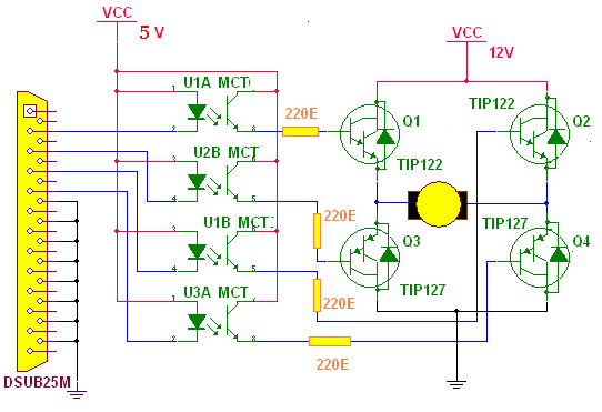
H-Bridge is standard, well known circuit and widely used as DC motor driver. Its schematic is as shown in the circuit tab 1. The circuit is made up of three major components optocoupler MCT2E, NPN darlington pair TIP122, PNP darlington pair TIP127. This is very standard circuit and can be used to drive any industrial motor DC motor with maximum voltage of 100V and maximum current of 5A.
Connections:- NPN and PNP Darlington pairs are connected in bridge configuration as shown. DC motor is connected as a load to bridge circuit. Bases of all four darlington pairs are connected to 25 pin D-type connector through opto-couplers. Function of opto-coupler is to provide good isolation between PC and H-bridge circuit. In all opto-couplers, anode of LED and collector of phototransistor is tied to Vcc. cathodes are connected with respective data pins D0 to D3. Emitters of phototransistor are connected to bases of respective. Darlington pair through current limiting resistor 220E. All the Darlington pairs have inbuilt reverse diode that is for freewheeling action.
Operation:-
now when you apply low logic to pin pins 2 & 3 and high logic to pins 4 & 5, U1A and U2B will start conducting and provide high logic to bases of Q1 & Q3. U1B and U3A won’t conduct so bases of Q2 & Q4 will be on low logic. this will turn on Q1 & Q4 current will flow from supply – Q1 – (+Ve) terminal of motor – (-Ve) terminal of motor – Q4 – Ground. So motor will rotate in one direction. For this we have to apply HEX data word 0C (0000 1100) on LPT port.
Same way when you give low logic to pin no. 4-5 and high logic to pins 2-3, Q2 and Q3 will turn on and current will flow from supply – Q2 – (-Ve) terminal of motor – (+Ve) terminal of motor – Q3 – Ground. So motor will rotate in another direction. For this we have to apply HEX data word 03 (0000 0011) on LPT port.
Thus simply by switching the logic from high to low and low to high in between these four pins (2, 3, 4, and 5) you can change the direction of motor.
Now rather than directly giving high logic to pins if we apply PWM wave to it then during ON period of wave both transistors are closed switch (conducts) and during OFF period they are open switch (do not conduct) so every time average voltage is fed to motor. As you go on increasing pulse width (increasing ON period and decreasing OFF period) of PWM wave the avg. Voltage given to motor is increased and so the speed also increases. Same way if you decrease pulse width (increase OFF period and decrease ON period) of PWM waves the avg. voltage decreases and so the speed also decreases.
Here in this project, generating PWM wave on these pins (2, 3, 4 and 5) as well as switching the transistors to change the direction of motor is done by software program which is written in C++ programming language.
Software:-
Main function of this software is to
· Switch between transistors T1-T4 and T2-T3 to change direction of motor
· Generate PWM on pins (either on 2-3 or on 4-5) to vary speed of motor
Software is mainly divided in three parts
1. Graphics
2. PWM generation
3. mouse interfacing
Graphics:- This part generates complete view of control panel. It draws buttons like clockwise, anticlockwise, speed increase/decrease, displays instructions, draws borderline, writes text like “Speed”, “Speed factor”, displays speed factor etc. That means it prepares whole appearance of program screen.
PWM Generation
PWM Generation:- Generating PWM on parallel (LPT) port data pins (D0-D7) using C++ is very simple. For ON period you have to apply high logic (1 means 3.49V) on that data pin and low logic (0 means 0.09V) for OFF period of pulse. The base frequency over which PWM is generated is 200Hz. So the time period is 50 millisecond (ms). First when speed factor (d) is zero, program generates square wave of 50% duty cycle (25ms ON period and 25ms OFF period) on two parallel port pins (either on pin no. 2 &3 or on pin no. 4 & 5). This speed factor is added to the ON time period (25 + d) and subtracted from OFF time period (25 – d). So as you increase this factor the ON time period will increase and with the same factor OFF time period will decrease (suppose d=5 then ON time is 30 and off time is 20) so the base frequency 200Hz will not change. Same manner when you decrease speed factor ON time will decrease and OFF time will increase again frequency remains same. This you can easily understood with these waveforms.

Note:- You can increase the speed factor till you reach to min limit of OFF time period (5 ms). After that there won’t be any further increment in speed factor and program will display a message “Max Speed”. In same manner you can’t further decrease speed factor when you reach min limit of ON period (5 ms). When you reach this limit program will display message “Min Speed”.
Mouse interfacing
Mouse interfacing:- This is the most interesting part in whole program. User can do his/her all task by mouse click. To understand how mouse is interfaced in this program you have to go through whole theory of hardware interfacing using C++. I am not discussing about whole theory here but giving you the reference. You can refer the chapter “mouse interfacing” in book named “Let Us C” by Mr. kanitkar. In this program there are four functions that handles mouse event
1. initmouse()
2. resmptr(int p, int q, int r, int s)
3. showmptr()
4. getmpos(int *t, int *u, int *v)
initmouse function loads mouse driver in to the program. In this function we are passing 0 value through input union REGS to int86( ) function. This function will return some nonzero value through output union REGS to main program. If this function returns value zero (0), it means mouse driver is not loaded. So program displays message “mouse driver is not loaded” and also it shuts the program screen off using exit( ) function.
Resmptr(int p, int q, int r, int s) function restrict mouse movement within the boundary specified by the four variables passed to it. We pass all these boundary limits through input union REGS to int86 () function. So int86( ) function will restrict the mouse movement out of this boundary.
Showmptr( ) function displays mouse pointer on program screen. For this just we have to pass the value 1 through input union REGS to int86 ( ) function. And int86 function will shows mouse pointer on screen
Getmpos (int *t, int *u, int *v) performs two tasks. It determines whether mouse button is pressed or not and it captures current mouse pointer position from screen. We have to pass the value 3 through input union REGS to int86 () function. This function will returns the x and y co-ordinates of mouse pointer and also returns value 1 if mouse button (left) is pressed or 0 if button is not pressed.
How program works?
Until and unless you press any key you can see the program screen displaying control panel for DC-Motor speed and direction control. Program continuously checks for mouse click event. Whenever there is a mouse click instantly getmpos() function captures x and y co-ordinates of mouse pointer and pass it to the main program. Main program decides on which position click event has happened and if it happened on any button (clockwise, anticlockwise etc.) Then, it performs the desired task. For example you click on speed increase button, program gets co-ordinate and directly switches to that IF loop, increase the speed factor and also displays it on screen.
How to rotate DC Motor
How to rotate DC Motor
First prepare the hardware as shown in schematic. You can prepare it even on bread board also (no need to solder) because there are only 8 components (4 optocouplers and 4 darlington pairs). Connect DB25 connector with PC’s LPT port. Apply 12V supply to supply terminals and connect the DC motor with its terminals. Now run “DC-Speed.exe” on your computer. You will see control panel on your screen. Now switch on the 12V supply. Move your mouse pointer to any button.
To rotate motor clockwise or anticlockwise, press and hold clockwise/anticlockwise button with left mouse button. Motor will rotate in desired direction till the button is pressed and you will also hear a sound. Motor will stop rotating when you release button. If you press clockwise button and motor rotates anticlockwise then just reverse the terminals of motor
To increase/decrease the speed of motor just press speed increase/decrease button with left mouse button once. Sweet sound is generated and speed factor will be incremented/ decremented and displayed on screen. Pressing these buttons more than one time will increase/decrease the speed factor by same amount.
Circuit Diagrams
Filed Under: Electronic Projects

Questions related to this article?
👉Ask and discuss on Electro-Tech-Online.com and EDAboard.com forums.
Tell Us What You Think!!
You must be logged in to post a comment.