This article explains how one can change the direction and speed of mini DC motor using very simple circuit built using readily and easily available handy components. First we will see how we can change the direction of motor and then we will see how we can vary the speed of DC motor. Then I will explain very simple DC motor controller circuit that changes direction as well as varies the speed of DC motor. So let us start.
Tell me how to change direction of rotation of DC motor?
It is very simple. Most of mini DC motors have two terminals because they are series type (armature and field windings are connected in series) DC motors. Please refer the figure given below.
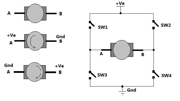
Fig. 1: Image showing H-Bridge circuit used for controlling direction of rotation of a DC Motor
As shown in figure there are two terminals ‘A’ and ‘B’ of DC motor. Now if we connect terminal A with +Ve supply and terminal B with –Ve supply or ground the current will flow from motor from A to B and motor will rotate in one direction – say clockwise (CW) or forward direction. Now as shown in second figure we change the supply terminals. Now B is connected with +Ve and A is connected to ground. The current will flow from motor from B to A and motor will rotate in other direction (counter clockwise – CCW or reverse).
So next question is how to give reversible supply to motor?
The arrangement is shown in right side of figure. Four switches are connected in between +Ve supply and ground and DC motor is connected in between two switches as shown. Such circuit arrangement is known as H-bridge because it looks like letter ‘H’ (H-bridge circuits are most widely used in DC motor drivers). Let us see how it gives reverse supply to motor.
If SW1 and SW4 are pressed simultaneously then current will flow from +Ve – SW1 – A – B – SW4 – Gnd. So motor will rotate in one direction. Open (release) SW1 and SW4 to stop motor. Now if SW2 and SW3 are pressed current will flow from +Ve – SW2 – B – A – SW3 – Gnd. So motor gets reverse supply and it will rotate in another direction.
(Caution: care has to be taken that SW1 and SW3 or SW2 and SW4 must not be pressed simultaneously otherwise it will short circuit the supply)
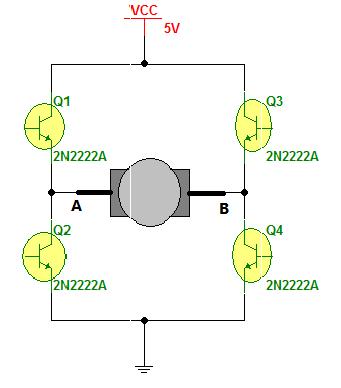
Fig. 2: Circuit Diagram of H-Bridge built by transistor for controlling DC motor speed and rotation
The circuit replaces the switches with NPN type transistors. We all know that transistor works as switch. For NPN transistor if we give +Ve input to base it will turn ON and if we give 0 input it will be turned OFF.
So in this circuit if Q1 and Q4 are turned ON simultaneously the motor will rotate forward and if Q2 and Q3 are turned ON then motor will rotate reverse.
Isn’t it very simple?
Motor can be rotated forward and reverse using 4 transistors only.
Now let us move to vary the speed of DC motor. The DC motor speed varies as applied input voltage varies. As you increase applied input voltage the speed will increase and vice versa. Applying max rated voltage will rotate motor at full speed (caution: do not apply more than max rated voltage to motor otherwise motor windings may get burnt).
Now the question is how to apply variable voltage to motor?
One of the very popular methods for generating variable DC voltage is pulse width modulation (PWM). It is explained in figure given below.
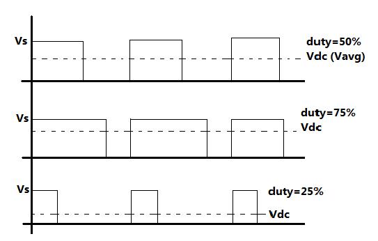
Fig. 3: Graph showing Pulse Width Modulation for controlling speed of DC Motor
Pulse width modulation means varying the width (duty) of pulse. Width means ON time Ton of pulse. The average output voltage (Vdc or Vavg) is given by equation
Vdc = [Ton / (Ton+Toff)] × Vs
It directly depends upon Ton. As shown in above figure if duty is 50% the average output voltage Vdc is exactly the half of Vs. If duty is increased to 75%, Vdc also increases to 3/4th of Vs and if duty is decreased to 25%, Vdc reduces to 1/4th of Vs. Thus as pulse width varies the average output voltage varies. So we have to apply PWM to DC motor to vary its speed.
Obviously the next question is how to generate PWM?
Any guesses………..?
Yes, the answer is IC NE555. This chip can be used to generate PWM. Here is the IC NE555 circuit to generate PWM output
Connections: IC NE555 is connected in astable mode. +12 biasing is given to Vcc pin (8). Reset pin (4) is also given +Ve supply to enable internal flip flop. Two diodes connected back to back at discharge pin (7). One 1K resistor is connected between Vcc and discharge pin. A 10 K pot along with two diodes D1 and D2 is connected between threshold pin (6) and discharge pin in such a way that as it is increased, the resistance for charging capacitor increases and resistance for discharging capacitor decreases.
Operation: when supply is given to circuit, the capacitor charges through R2-D2-R1A. The output of circuit is high. When capacitor charges to 2/3 Vcc, the internal threshold comparator gives output that makes circuit output low. So if R1 is increased – R1A is more – capacitor charging time increased – high output time (Ton) is more – duty cycle is more. Afterwards capacitor discharges through R1B – D1. So if R1 is decreased – R1B is more – capacitor discharging time is increased – low output time (Toff) is more – duty cycle is less.
So this circuit generates PWM and width of pulse varies as pot R1 is varied.
Finally we need transistor H bridge circuit to alter the direction of DC motor and IC NE555 based PWM generator circuit to vary the speed of DC motor. Here is the complete circuit.
The output of PWM generator circuit is given to H-Bridge circuit through SPDT switch. As we change the position of SPDT switch, the signal is either applied to Q1 and Q4 or Q2 and Q3. So the SPDT switch alters the direction of motor. And the pot R1 varies width of output pulse applied to H-bridge circuit. So it varies the speed of motor.
Here is the snap of circuit built on bread board
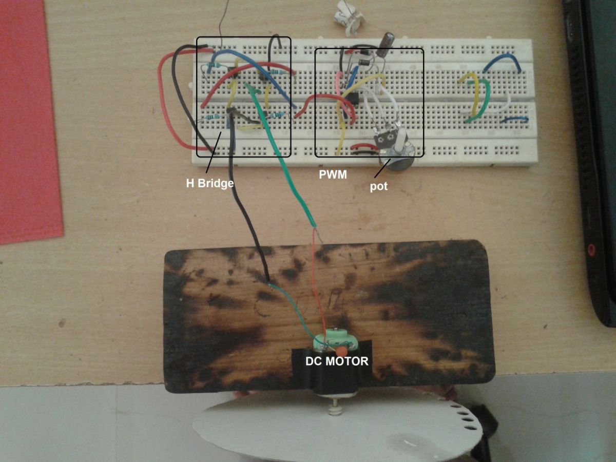
Fig. 4: Prototype of H-Bridge Circuit on a breadboard
So this is the simple circuit control speed and direction of DC motor. It can control DC motors having 12 V or 500 mA current ratings. For higher voltage or current rating motors one can use darlington pair transistors (TIP122, TIP142 etc) or power MOSFETS (IRF series) or even SCR (TYN series)
Circuit Diagrams
| Circuit-Diagram-555-IC-Based-Pulse-Width-Modulation-PWM-Generator | 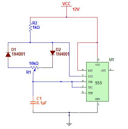 |
| Circuit-Diagram-H-Bridge-Used-Controlling-Direction-DC-Motor | 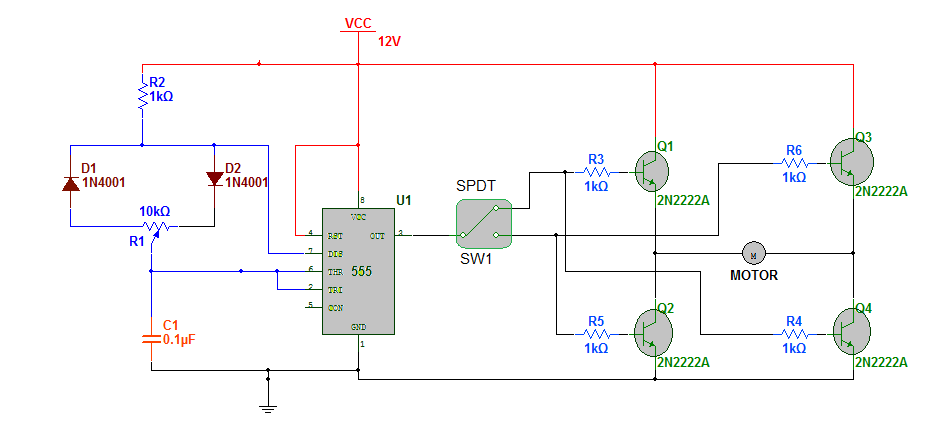 |
Project Video
Filed Under: Circuit Design
Filed Under: Circuit Design


Questions related to this article?
👉Ask and discuss on Electro-Tech-Online.com and EDAboard.com forums.
Tell Us What You Think!!
You must be logged in to post a comment.