DC motors are widely used in different machines, mechanism and motion control in manufacturing and processing industries. In these machines/mechanisms it is required to control speed of motor or number of rotations of motor or may be both. For example
-
To release thread (or wire) of desire length from a bobbin, it is required to rotate bobbin for specific number of rotation. Also there is provision for controlling a speed at which thread is released. So here it is required to rotate bobbin at required speed and for required number of rotations only
-
In coil winding machine it is required make specific number of coil turns. It is done by rotating motor for specific number of rotations. Also it is required to vary the motor speed to speed up/down the operation
-
In conveyor belt application, to move the object to exact distance it is required to rotate motor for desire number of rotations
Thus we may list out many numbers of such examples and applications where it is required to control rotations and speed of DC motor.
The given project is demonstration of controlling rotations and speed of DC motor. Its an example of close loop control system. It utilizes feedback loop. It counts actual number of motor rotations and gives as a feedback to system. The system compares set rotations with actual motor rotations and stops motor when they match. It also controls speed of motor from 10% to 100%. The project utilizes micro controller ATMega32 to control DC motor, LCD for display parameters and opto-interrupt sensor count motor rotations and provide feedback.
Circuit description:
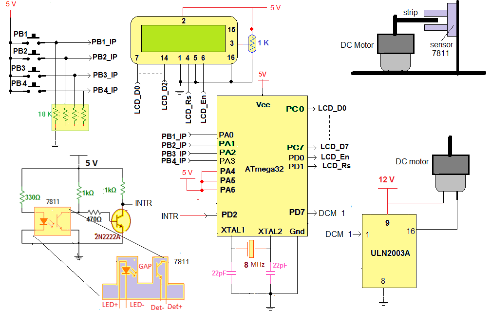
As shown in figure, the circuit is built using AVR micro controller ATMega32, darlington chip ULN2003A, 16×2 LCD, opto-interrupt sensor MOC7811 and other few components like push buttons, resistors, crystal etc.
Four push buttons are connected to PORTA pins PA0 – PA3 such that when button is pressed it gives logic ‘1’ input to pin. They are used to enter rotation and speed and to rotate motor.
LCD is connected to PORTC and PORTD. Its data pins are connected to PORTC and two control pins Rs and En are connected to PD0 and PD1 respectively. LCD displays number of rotations and speed of DC motor.
PORTD pin PD7 drives DC motor through Darlington pair chip ULN2003A. This pin is connected to input (1) of ULN2003A and the output (16) of ULN2003A is connected to one terminal of motor. Other terminal of motor is connected to 12 V supply.
So when logic ‘1’ input is given from micro controller to PD7, the Darlington pair conducts and motor starts rotating.
Opto-interrupt sensor MOC7811 internally consists of IR LED and photo transistor. The internal IR LED is forward biased to make it continuously on. A current limiting resistor of 330E is used to limit the current through it. The output of photo transistor is given as input to another NPN transistor that is connected in switch mode. The final output of sensor circuit is taken from collector of NPN transistor. This output is given to external interrupt 0 input pin PD2 (17) of ATMega32.
Here are the snaps of circuit arrangement

Fig. 1: Prototype of AVR ATMega16 based DC Motor Speed Control Circuit

Fig. 2: Prototype of AVR ATMega16 based DC Motor Speed Control after installation
Circuit operation:
The motor is stop initially. The message is display on LCD to enter required number of motor rotations as “Set rotations”
User can select required number of rotations by pressing button 1 or 2. Button 1 is used to increase number of rotations by 5 and button 2 is to decrease number of rotations by 5. Minimum numbers of rotations are 10.
Once desire numbers of rotations are selected, user has to press enter (button 3). The LCD shows message as “Rotations set to xx”
After 2 second, the user is asked to enter required speed. The message is displayed on LCD as “Set motor speed”
User can set speed from 10% to 100% in step of 10 by pressing same button1 and button2. Button 1 is used to increase speed by 10% and button 2 is to decrease speed by 10%.
Once desire speed is set, again user has to press enter. The LCD shows message as “Speed is set to xx%”
Now user is asked to start the motor and LCD shows message “press rotate”. When user presses rotate button (button 4), the micro controller applies PWM as per selected speed to motor and motor starts rotating at desired speed. The LCD shows speed and rotations of motor.
As the motor rotates one revolution, a strip attached to the shaft of motor passes through the gap of opto-interrupt sensor. That interrupts IR light falling on photo transistor for fraction of second. So photo transistor gives very short duration positive pulse. This positive pulse is inverted by NPN transistor and it gives short duration negative pulse. This negative pulse generates interrupt for micro controller. Micro controller counts these numbers of interrupts as numbers of rotations of motor.
When motor completes desire numbers of rotations, micro controller stops applying PWM so motor stops
After 2 second, again user is asked to enter desire rotations for next operation and this cycle continuous.
Software program:
The micro controller ATmega32 is the main building block of this project because it performs all the tasks like
-
Take user input from push buttons to set speed and rotations, run motor etc
-
Rotates motor at desire speed using PWM technique
-
Displays motor speed, rotations and various messages on LCD
-
Counts actual motor rotations and
To implement all above functionalities the software program is downloaded into internal ROM (FLASH) of this micro controller. Here is the C program with necessary comments.
Project Source Code
###
#include
#include
#include
#include
#define lcd_databus PORTC // PORTC is LCD data bus
#define lcd_cntr_port PORTD // PORTD is LCD control port
#define rs PD1
#define en PD0
//////////////////////// variable declaration /////////////////////////////
unsigned int speed_set_flag=0,rotation_set_flag=1;
unsigned int speed=25,speed_value=10,num_of_rotations=10,motor_rotations=0;
///////////////// function to send data to LCD/////////////////////////////
void senddata(unsigned char data)
{
_delay_ms(2); // wait till LCD is busy
lcd_cntr_port=(1<
lcd_databus=data; // send data
lcd_cntr_port=(1<
lcd_cntr_port =(1<
}
/////////////////// function to send command to LCD /////////////////////
void sendcmd(unsigned char cmd)
{
_delay_ms(2); // wait till LCD is busy
lcd_cntr_port = (0<
lcd_databus=cmd; // send command
lcd_cntr_port = (1<
lcd_cntr_port = (0<
}
////////////////////// function to print string on LCD ////////////////
void printstr(char *s)
{
unsigned int l,i;
l = strlen(s); // get the length of string
for(i=0;i
{
senddata(*s); // write every char one by one
s++;
}
}
/////////////////// function to print integer value on LCD ///////////////
void display_data(unsigned int value)
{
unsigned char ascii_value[3];
unsigned int tmp,t;
if(value>=100) // if value is of 3 digits
{
tmp = value%10; // separate last digit
ascii_value[2] = tmp+0x30; // convert it into ASCII
value = value/10;
tmp = value%10; // likewise convert
ascii_value[1] = tmp+0x30; // all 3 digits into ASCII
value = value/10;
ascii_value[0] = value+0x30;
}
else if (value>=10)
{
tmp = value%10; // else if value is of 2 digits
ascii_value[1] = tmp+0x30; // separate digits and convert
value = value/10; // them into ASCII
ascii_value[0] = value+0x30;
ascii_value[2] = 0x20; // make last digit space
}
else if(value<10) // if value is of 1 digit
{
ascii_value[0] = value+0x30; // convert it into ASCII
ascii_value[2] = 0x20; // rest two digits space
ascii_value[1] = 0x20;
}
for(t=0;t<3;t++) senddata(ascii_value[t]); // print value
}
////////////////////// function to initialize LCD ////////////////////////
void lcd_init()
{
sendcmd(0x3C); // 8-bits/char 7x5 dots/char
sendcmd(0x0E); // screen and cursor ON
sendcmd(0x01); // clear LCD
printstr("DC Motor speed &"); // display project name
sendcmd(0xC0);
printstr("rotation control");
}
/////////////////////// function for up-arrow key //////////////////////
void up_arrow_key()
{
if(speed_set_flag==1) // either set speed
{
if((speed<250) && (speed_value<100))
{
speed +=25; // inc speed by inc PWM width
speed_value+=10; // inc display speed value
}
sendcmd(0xC0);
display_data(speed_value); // display the value
senddata('%');
}
else if(rotation_set_flag==1) // or set rotations
{
num_of_rotations+=5; // inc rotations
sendcmd(0xC0);
display_data(num_of_rotations); // display them
}
}
///////////////////// function for down-arrow key ///////////////////////
void down_arrow_key()
{
if(speed_set_flag==1) // either set speed
{
if((speed>25) && (speed_value>10))
{
speed -=25; // dec speed by dec PWM width
speed_value-=10; // dec display speed value
}
sendcmd(0xC0);
display_data(speed_value); // display speed
senddata('%');
}
else if(rotation_set_flag==1) // or set rotations
{
if(num_of_rotations>10) num_of_rotations-=5; // dec rotations
sendcmd(0xC0);
display_data(num_of_rotations); // display rotations
}
}
///////////////////////// function for enter key ////////////////////////
void enter_key()
{
if(speed_set_flag==1) // when pressed to set speed
{
sendcmd(0x80);
printstr("speed is set to "); // display message and
sendcmd(0xC0);
display_data(speed_value); // speed value
senddata('%');
speed_set_flag=0; // reset the flag
_delay_ms(2000); // and after 2 second
sendcmd(0x01);
printstr("press rotate"); // display message
}
else if(rotation_set_flag==1) // when pressed to set rotations
{
sendcmd(0x01);
printstr("rotations set to"); // display set rotation
sendcmd(0xC0);
display_data(num_of_rotations); // value
rotation_set_flag=0; // reset the flag
_delay_ms(2000); // wait for 2 sec
sendcmd(0x01);
printstr("set motor speed"); // again display message
sendcmd(0xC0);
display_data(speed_value);
senddata('%');
speed_set_flag=1;
}
}
//////////////////////// function to rotate motor ///////////////////////
void rotate_motor()
{
sendcmd(0x01);
printstr("speed:"); // display motor speed
display_data(speed_value);
senddata('%');
sendcmd(0xC0); // and actual number of
printstr("rotations:"); // rotations
OCR2 = speed; // set width for PWM
///////// rotate motor till desire rotations complete///////
while(num_of_rotations!=motor_rotations)
{
TCCR2 = 0x6A; // start timer to generate PWM
PORTC=0x01;
}
PORTC = 0x00;
TCCR2 = 0x00; // stop timer
motor_rotations=0; // reset motor rotations
rotation_set_flag=1; // set rotation flag again
_delay_ms(2000); // delay for 2 sec
sendcmd(0x01); // clear LCD
printstr("set rotations"); // again display message for
sendcmd(0xC0); // next operation
display_data(num_of_rotations);
}
//////////////////////////// main function ////////////////////////////////
int main(void)
{
DDRB=0xFF; // configure ports as input or output
DDRC=0x01;
DDRD=0x83;
DDRA=0x00;
PORTD=0x00;
PORTB=0x00;
PORTC=0x00;
MCUCR = (1<
GICR=(1<
sei(); // enable global interrupt
lcd_init(); // initialize LCD
_delay_ms(2000); // wait for 2 seconds
sendcmd(0x01); // clear LCD and
printstr("set rotations"); // display message
sendcmd(0xC0);
display_data(num_of_rotations);
while(1)
{
while(PINA==0xF0); // wait till no button is pressed
switch(PINA)
{
case 0xF1: // for 1st button
up_arrow_key(); // inc speed or num of rotations
_delay_ms(200); // key debounce delay
break;
case 0xF2: // for 2nd button
down_arrow_key(); //dec speed or num of rotations
_delay_ms(200);
break;
case 0xF4: // for 3rd button
enter_key(); // set speed or rotations
_delay_ms(200);
break;
case 0xF8: //for 4th button
rotate_motor(); // rotate motor
_delay_ms(200);
break;
}
}
}
////////////////////// external interrupt 0 function //////////////////////
ISR(INT0_vect)
{
motor_rotations++; // inc motor rotations
sendcmd(0xCA);
display_data(motor_rotations); // display it on LCD
}
###
Circuit Diagrams
Project Video
Filed Under: Electronic Projects
Filed Under: Electronic Projects

Questions related to this article?
👉Ask and discuss on EDAboard.com and Electro-Tech-Online.com forums.
Tell Us What You Think!!
You must be logged in to post a comment.