Engineers Garage

  • Projects and Tutorials
    • Electronic Projects
      • 8051
      • Arduino
      • ARM
      • AVR
      • PIC
      • Raspberry pi
      • STM32
    • Tutorials
    • Circuit Design
    • Project Videos
    • Components
  • Articles
    • Tech Articles
    • Insight
    • Invention Stories
    • How to
    • What Is
  • News
    • Electronic Products News
    • DIY Reviews
    • Guest Post
  • Forums
    • EDABoard.com
    • Electro-Tech-Online
    • EG Forum Archive
  • Digi-Key Store
    • Cables, Wires
    • Connectors, Interconnect
    • Discrete
    • Electromechanical
    • Embedded Computers
    • Enclosures, Hardware, Office
    • Integrated Circuits (ICs)
    • Isolators
    • LED/Optoelectronics
    • Passive
    • Power, Circuit Protection
    • Programmers
    • RF, Wireless
    • Semiconductors
    • Sensors, Transducers
    • Test Products
    • Tools
  • EE Resources
    • DesignFast
    • LEAP Awards
    • Oscilloscope Product Finder
    • White Papers
    • Webinars
  • EE Learning Center
    • Design Guides
      • WiFi & the IOT Design Guide
      • Microcontrollers Design Guide
      • State of the Art Inductors Design Guide
  • Women in Engineering

DC Motor Speed Control using Chopper

By Ashutosh Bhatt

In many different applications it is required to control speed of DC motor. Some of the examples are

·         In treadmill machine it is required to vary the speed of motor that used to roll the belt

·         The speed of DC motor used in railway engines (traction) has to be varied

·         E-bikes, e-bicycles, e-scooters also runs on DC motor and to vary their speed it is required to control speed of DC motor

·         DC motors are also used in portable sewing machine, drill machine etc, in which speed control of motor is provided for different operation

One of the popular methods of speed control of DC motor is using chopper. Chopper is a device that gives variable DC output from applied fixed DC input. It simply chops fixed DC and generates variable DC. Let us first understand how it generates variable DC.

Block Representation of Chopper circuit used to control rotation of DC Motor

Fig. 1: Block Representation of Chopper circuit used to control rotation of DC Motor

As shown in figure the chopper supplies fixed DC voltage to motor. When chopper is ON motor gets supply but when chopper is off motor does not get the supply. So as shown in figure let us say chopper is on for Ton time and it is off for Toff time. So depending upon the Ton and Toff time the DC voltage applied to motor is

Vdc = [Ton / (Ton + Toff)] × Vfixed

But                                                         Ton + Toff = Ttotal

So                                                           Vdc = [Ton / Ttotal] × Vfixed

Here Ton / Ttotal is called duty cycle. So as duty cycle is more the average DC voltage supplied to motor is more and so speed of motor is increased. So as duty cycle is varied by varying on and off time of chopper, the speed of motor can be varied.

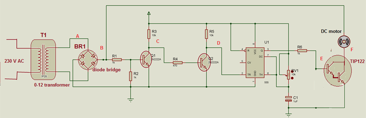
The given circuit demonstrates one of such chopper circuit using Zero Cross Detector (ZCD), timer IC NE555 and darlington amplifier TIP122 used as chopper device. The circuit chops rectified DC output and varies the speed of DC motor.


Circuit Description

·         230V @ 50 Hz AC is applied at the primary of transformer T1 (0-12 VAC, 500 mA). It’s secondary is connected with AC input terminals of bridge rectifier BR1.

·         Rectified output is given to base of transistor Q1 through voltage divider formed by resistors R1 (1K) & R2 (1K).

·         Collector output of Q1 is fed to base of transistor Q2 through R4 (470Ω). Q1 and Q2 both are connected in switch configuration as shown.

·         The output of Q2 is applied at the trigger input of NE555 chip U1. It is configured in monostable mode. Timing components RV1 (10K pot) and C1 (1 µF) decides width of output pulse

·         Output of U1 is applied to base of darlington transistor TIP122 through current limiting resistor R6

·         The DC motor is connected between rectified output and collector of TIP122. The emitter of TIP122 is connected to ground

(Check the circuit diagram tab for complete circuit for DC motor speed control using chopper)


Circuit Operation

Let us understand the circuit operation with the help of waveforms at different points A, B, C, D, E and F

Timing Diagram of Signals at various stages of the chopper circuit

Fig. 2: Timing Diagram of Signals at various stages of the chopper circuit

·         Step down transformer T1 steps down 230 VAC into 12 VAC as shown as waveform 1 above figure at point A

·         This AC input is given to bridge rectifier. Bridge rectifier will produce rectified DC output as shown in second waveform if above figure at point B

·         This rectified output is given to base of transistor Q1. Because transistor Q1 is connected in switch configuration, when the input at the base becomes lower than 0.7 V it comes into cutoff and produces very short duration positive pulse at point ‘C’. That is shown as 3rd waveform in figure

·         As this positive pulses are given to Q2 which is again connected in switch configuration, it will produce negative pulse at point ‘D’ of same width of positive pulse. This is shown as 4th waveform

·         These negative pulses are applied to trigger input of NE555 chip connected in monostable mode. So it will generate high output every time when it gets this negative pulse. Its time period can be varied from 0 milisecond  to max 10 milisecond using 10 K pot

·         As per the waveforms given in below figure let us understand 2 different cases with pulse width of NE555 3 ms and 8 ms

·         As shown a second waveform in above figure, the NE555 will generate high output when gets negative pulse at its trigger input. For first case the width of pulse is 3 ms

·         Because this pulse is given to base input of TIP122, it is turned ON till pulse is high. When TIP122 is ON the motor gets chopped rectified output as shown in 3rd waveform in figure. Out of total 10 ms time, the motor gets DC waveform for 3 ms only

·         So average voltage applied to DC motor is less (as shown in waveform) and its speed is also less

Timing Diagram of Output Waveforms from the Chopper Circuit

Fig. 3: Timing Diagram of Output Waveforms from the Chopper Circuit

·         As shown in 4th and 5th waveforms, now the time period (pulse width) of NE555 is increased to 8 ms. So the rectified output applied to DC motor is also more – means average voltage applied to motor is more and its speed is more

·         Thus as time period (width of output pulse) of NE555 is varied from 0 ms to 10 ms, it gives chopped rectified DC wave to motor that will vary its speed from min to max.

Project Source Code

###

//Program to 

###


Circuit Diagrams

Circuit-Diagram-Chopper-DC-Motor-Speed-Control_0


Filed Under: Electronic Projects


Questions related to this article?
👉Ask and discuss on EDAboard.com and Electro-Tech-Online.com forums.


Tell Us What You Think!! Cancel reply

You must be logged in to post a comment.

HAVE A QUESTION?

Have a technical question about an article or other engineering questions? Check out our engineering forums EDABoard.com and Electro-Tech-Online.com where you can get those questions asked and answered by your peers!


Featured Tutorials

  • Introduction to Brain Waves & its Types (Part 1/13)
  • Understanding NeuroSky EEG Chip in Detail (Part 2/13)
  • Performing Experiments with Brainwaves (Part 3/13)
  • Amplification of EEG Signal and Interfacing with Arduino (Part 4/13)
  • Controlling Led brightness using Meditation and attention level (Part 5/13)
  • Control Motor’s Speed using Meditation and Attention Level of Brain (Part 6/13)

Stay Up To Date

Newsletter Signup

Sign up and receive our weekly newsletter for latest Tech articles, Electronics Projects, Tutorial series and other insightful tech content.

EE Training Center Classrooms

EE Classrooms

Recent Articles

  • What are the battery-selection criteria for low-power design?
  • Key factors to optimize power consumption in an embedded device
  • EdgeLock A5000 Secure Authenticator
  • How to interface a DS18B20 temperature sensor with MicroPython’s Onewire driver
  • Introduction to Brain Waves & its Types (Part 1/13)

Most Popular

5G 555 timer circuit 8051 ai Arduino atmega16 automotive avr bluetooth dc motor display Electronic Part Electronic Parts Fujitsu ic infineontechnologies integratedcircuit Intel IoT ir lcd led maximintegratedproducts microchip microchiptechnology Microchip Technology microcontroller microcontrollers mosfet motor powermanagement Raspberry Pi remote renesaselectronics renesaselectronicscorporation Research samsung semiconductor sensor software STMicroelectronics switch Technology vishayintertechnology wireless

RSS EDABOARD.com Discussions

  • Poly Spacing Effect
  • Thyristor Gate Drive
  • Passive Harmonics Filter
  • Variable Phase shift control circuit for PWM circuit
  • Avalanche Pulser

RSS Electro-Tech-Online.com Discussions

  • HV Diodes
  • Question about ultrasonic mist maker
  • Someone please explain how this BMS board is supposed to work?
  • DIY bluetooth speaker
  • Disabled son needs advice please
Engineers Garage
  • Analog IC TIps
  • Connector Tips
  • DesignFast
  • EDABoard Forums
  • EE World Online
  • Electro-Tech-Online Forums
  • Microcontroller Tips
  • Power Electronic Tips
  • Sensor Tips
  • Test and Measurement Tips
  • 5G Technology World
  • About Us
  • Contact Us
  • Advertise

Copyright © 2022 WTWH Media LLC. All Rights Reserved. The material on this site may not be reproduced, distributed, transmitted, cached or otherwise used, except with the prior written permission of WTWH Media
Privacy Policy | Advertising | About Us

Search Engineers Garage

  • Projects and Tutorials
    • Electronic Projects
      • 8051
      • Arduino
      • ARM
      • AVR
      • PIC
      • Raspberry pi
      • STM32
    • Tutorials
    • Circuit Design
    • Project Videos
    • Components
  • Articles
    • Tech Articles
    • Insight
    • Invention Stories
    • How to
    • What Is
  • News
    • Electronic Products News
    • DIY Reviews
    • Guest Post
  • Forums
    • EDABoard.com
    • Electro-Tech-Online
    • EG Forum Archive
  • Digi-Key Store
    • Cables, Wires
    • Connectors, Interconnect
    • Discrete
    • Electromechanical
    • Embedded Computers
    • Enclosures, Hardware, Office
    • Integrated Circuits (ICs)
    • Isolators
    • LED/Optoelectronics
    • Passive
    • Power, Circuit Protection
    • Programmers
    • RF, Wireless
    • Semiconductors
    • Sensors, Transducers
    • Test Products
    • Tools
  • EE Resources
    • DesignFast
    • LEAP Awards
    • Oscilloscope Product Finder
    • White Papers
    • Webinars
  • EE Learning Center
    • Design Guides
      • WiFi & the IOT Design Guide
      • Microcontrollers Design Guide
      • State of the Art Inductors Design Guide
  • Women in Engineering