Engineers Garage

  • Projects and Tutorials
    • Electronic Projects
      • 8051
      • Arduino
      • ARM
      • AVR
      • PIC
      • Raspberry pi
      • STM32
    • Tutorials
    • Circuit Design
    • Project Videos
    • Components
  • Articles
    • Tech Articles
    • Insight
    • Invention Stories
    • How to
    • What Is
  • News
    • Electronic Products News
    • DIY Reviews
    • Guest Post
  • Forums
    • EDABoard.com
    • Electro-Tech-Online
    • EG Forum Archive
  • Digi-Key Store
    • Cables, Wires
    • Connectors, Interconnect
    • Discrete
    • Electromechanical
    • Embedded Computers
    • Enclosures, Hardware, Office
    • Integrated Circuits (ICs)
    • Isolators
    • LED/Optoelectronics
    • Passive
    • Power, Circuit Protection
    • Programmers
    • RF, Wireless
    • Semiconductors
    • Sensors, Transducers
    • Test Products
    • Tools
  • EE Resources
    • DesignFast
    • LEAP Awards
    • Oscilloscope Product Finder
    • White Papers
    • Webinars
  • EE Learning Center
    • Design Guides
      • WiFi & the IOT Design Guide
      • Microcontrollers Design Guide
      • State of the Art Inductors Design Guide
  • Women in Engineering

Decimal counter designed in vhdl

By EG Projects

This tutorial is about designing a decimal counter in vhdl. I used xilinx to write code and for simulation i used Isim simulator. The decimal counter i designed starts from 0 and moves up to 999. Counter is working perfectly in simulation.     

What is Decimal Counter?

Decimal counter is same like a stop watch. Take example of a counter from 0 up to 100. In decimal counter same like stop watch the unit place starts from 0 and goes up to 9. When unit place reaches 9 it increments the tenth place by 1 and resets it self.  Again the unit place starts from 0 and counts up to 9, resets it self and increments the tenth place. When tenth place reaches 9 it resets it self now while increments the hundredth place
. An example of decimal counter is shown in the below picture.
Picture

The above decimal counter max range is 100 while the one i am going to design will count up to 999.

Decimal counter in vhdl

My goal is to design the same stop watch like counter known as decimal counter in vhdl. The logic is pretty simple first increment the unit place and when it reaches 9 increment the tenth place while resetting it self(unit place). 

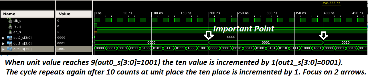
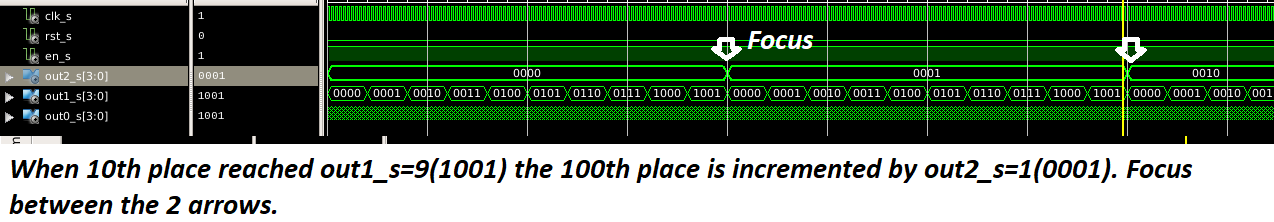
In the below simulation figure out0_s[3:0] is unit place port and out1_s[3:0] is tenth place port. Focus on the arrow points. When out0_s[3:0] unit place reaches 9(1001 is hexadecimal representation of whole number 9). The out1_s[3:0] tenth place is incremented by 1 and out0_s[3:0] is reset to 0.   

Decimal counter vhdl simulation-Unit place to 10 place increment

Decimal counter vhdl simulation-Unit place to 10 place increment

Now in the below figure out2_s[3:0] represents the hundredth place. Focus on the arrow points. When tenth place out1_s[3:0] reaches 9 the hundredth place increments by 1 and tenth place resets to 0. This whole process repeats until the decimal counter reaches maximum point which is 100 in our case. 
Decimal counter vhdl simulation-Tenth place to 100th place increment

Decimal counter vhdl simulation-Tenth place to 100th place increment

In simulation figures above it is hard to show the three unit, tenth and hundredth place in a single figure. So i split the figures.   
Project code starts with the necessary header files. Then comes the entity “decimal counter“. I aspect that you know about the libraries used in the project and you have know how of the entity and its architecture in vhdl. At least you must know what does entity and its architecture mean.

In entity their are three input ports. Reset port resets the decimal counter to 0. Enable port enables the decimal counter and at last the clock is input to the digital system. Which means that the system works on clock. The three outputs out0, out1 and out2 are decimal counter outputs. They represent unit place out0, tenth place out1 and hundredth place out2. The outputs are 4-bit wide because the max they count is 9 whose binary is 1001.    

In the architecture first few signals are defined. These signals are used in replacement of the output ports to count values internally and increment them. Internal signals are assigned to the output ports after necessary computation.

In the process block on reset all the internal signals are assigned 0. Note that the system is asynchronous. Which means reset does not depend on any state(rising/falling edge) of clock. But if reset in not active the control jumps to else state in which it is checked that if enable is activated? If enable is found activated then on the next rising edge of the clock the internal signals are assigned to the output ports. So every new output appears at output ports on rising edge of clock provided the enable is activated.  

After the process block the conditions on unit, tenth and hundredth digits are checked, calculated and assigned to internal signals. These signals at the end are assigned to the output ports. The use of FSM(finite state machine) is visible in the code. This tutorial only deals with the code flow. I supposed that you are familiar with the current and next state finite state machine.  

Decimal counter test bench

In the above decimal counter test bench the decimal counter entity is instantiated as component. Two processes are part of the test bench. First process is dealing with the clock. Its actually the input clock to the decimal counter. The frequency of clock is 20 ns.

The second process first resets the decimal counter. Reset is important. It assigns our internal signals initial value which is 000. Then after first rising edge of clock it deactivates the reset port and activates the enable port. After enable is activated i used a for loop to count to 1000 rising edges of clock. In the process of 1000 rising edges our decimal counter also reaches 999. After it i disabled the enable port.    

Project files


Filed Under: Microcontroller Projects, VHDL


Questions related to this article?
👉Ask and discuss on EDAboard.com and Electro-Tech-Online.com forums.


Tell Us What You Think!! Cancel reply

You must be logged in to post a comment.

HAVE A QUESTION?

Have a technical question about an article or other engineering questions? Check out our engineering forums EDABoard.com and Electro-Tech-Online.com where you can get those questions asked and answered by your peers!


Featured Tutorials

  • PS2 Keyboard To Store Text In SD Card Using Arduino Circuit Setup On Breadboard
    How To Use PS2 Keyboard To Store Text In SD Card Using Arduino- (Part 42/49)
  • Wireless Path Tracking System Using Mouse, XBee And Arduino Circuit Setup On Breadboard
    How To Make A Wireless Path Tracking System Using Mouse, XBee And Arduino- (Part 43/49)
  • How to Make a Wireless Keyboard Using Xbee with Arduino- (Part 44/49)
  • Making Phone Call From GSM Module Using Arduino Circuit Setup On Breadboard
    How to Make Phonecall From GSM Module Using Arduino- (Part 45/49)
  • How to Make a Call using Keyboard, GSM Module and Arduino
    How To Make A Call Using Keyboard, GSM Module And Arduino- (Part 46/49)
  • Receiving SMS Using GSM Module With Arduino Prototype
    How to Receive SMS Using GSM Module with Arduino- (Part 47/49)

Stay Up To Date

Newsletter Signup

Sign up and receive our weekly newsletter for latest Tech articles, Electronics Projects, Tutorial series and other insightful tech content.

EE Training Center Classrooms

EE Classrooms

Recent Articles

  • Renesas delivers intelligent sensor solutions for IoT applications
  • Microchip Technology releases AVR-IoT Cellular Mini Development Board
  • Qualcomm acquires Cellwize to accelerate 5G adoption and spur infrastructure innovation
  • MediaTek’s chipset offers high-performance option for 5G smartphones
  • Nexperia’s new level translators support legacy and future mobile SIM cards

Most Popular

5G 555 timer circuit 8051 ai Arduino atmega16 automotive avr bluetooth dc motor display Electronic Part Electronic Parts Fujitsu ic infineontechnologies integratedcircuit Intel IoT ir lcd led maximintegratedproducts microchip microchiptechnology Microchip Technology microcontroller microcontrollers mosfet motor powermanagement Raspberry Pi remote renesaselectronics renesaselectronicscorporation Research samsung semiconductor sensor software STMicroelectronics switch Technology vishayintertechnology wireless

RSS EDABOARD.com Discussions

  • Co-simulation setup in HFSS
  • How do we test an antenna for its receiver capability?
  • highest frequency capture with arduino input capture
  • Limits of duty cycle for ICM7555 IC?
  • Help identifying drop in ssignal

RSS Electro-Tech-Online.com Discussions

  • ICM7555 IC duty cycle limit at high frequency?
  • writing totals in Eprom
  • undefined reference header file in proteus
  • How to test phone socket?
  • intro to PI
Engineers Garage
  • Analog IC TIps
  • Connector Tips
  • DesignFast
  • EDABoard Forums
  • EE World Online
  • Electro-Tech-Online Forums
  • Microcontroller Tips
  • Power Electronic Tips
  • Sensor Tips
  • Test and Measurement Tips
  • 5G Technology World
  • About Us
  • Contact Us
  • Advertise

Copyright © 2022 WTWH Media LLC. All Rights Reserved. The material on this site may not be reproduced, distributed, transmitted, cached or otherwise used, except with the prior written permission of WTWH Media
Privacy Policy | Advertising | About Us

Search Engineers Garage

  • Projects and Tutorials
    • Electronic Projects
      • 8051
      • Arduino
      • ARM
      • AVR
      • PIC
      • Raspberry pi
      • STM32
    • Tutorials
    • Circuit Design
    • Project Videos
    • Components
  • Articles
    • Tech Articles
    • Insight
    • Invention Stories
    • How to
    • What Is
  • News
    • Electronic Products News
    • DIY Reviews
    • Guest Post
  • Forums
    • EDABoard.com
    • Electro-Tech-Online
    • EG Forum Archive
  • Digi-Key Store
    • Cables, Wires
    • Connectors, Interconnect
    • Discrete
    • Electromechanical
    • Embedded Computers
    • Enclosures, Hardware, Office
    • Integrated Circuits (ICs)
    • Isolators
    • LED/Optoelectronics
    • Passive
    • Power, Circuit Protection
    • Programmers
    • RF, Wireless
    • Semiconductors
    • Sensors, Transducers
    • Test Products
    • Tools
  • EE Resources
    • DesignFast
    • LEAP Awards
    • Oscilloscope Product Finder
    • White Papers
    • Webinars
  • EE Learning Center
    • Design Guides
      • WiFi & the IOT Design Guide
      • Microcontrollers Design Guide
      • State of the Art Inductors Design Guide
  • Women in Engineering