

Fig. 2: Block Diagram of LM358 Audio Pre Amplifier
Circuit Connections –
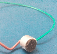
The biasing circuit for this microphone has been shown below –
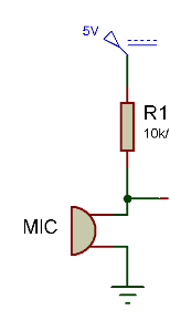
Fig. 4: Circuit Diagram of Electret Microphone Biasing
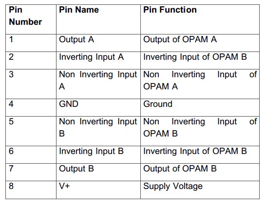
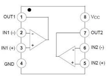
In this circuit, only one of its OPAM is used as an inverting amplifier. The inverting amplifier has negative feedback which makes them better than non- inverting amplifiers.

Fig. 7: Typical Image of LM358 IC
The inverting amplifier changes the phase of output (signal amplitude) by 180 degrees with the input (signal amplitude). The inverting amplifier changes the phase of output (signal amplitude) by 180 degrees with the input (signal amplitude). However, this phase inversion does not affect the audio signal as human ears are response only to the intensity of the sound. The intensity is the energy flowing through an area in a given time, expressed in joule/s/m2. The energy of the wave is proportional to the square of its amplitude. So for a unitarea, the intensity is also proportional to the square of the amplitude.

Fig. 8: Prototype of LM358 Audio Pre Amplifier

So, it can be observed that the input audio signal from the microphone is successfully leveled up to the line voltage. So, the pre-amplifier is working at its best.
You may also like:
Project Video
Filed Under: Electronic Projects
Filed Under: Electronic Projects






Questions related to this article?
👉Ask and discuss on Electro-Tech-Online.com and EDAboard.com forums.
Tell Us What You Think!!
You must be logged in to post a comment.