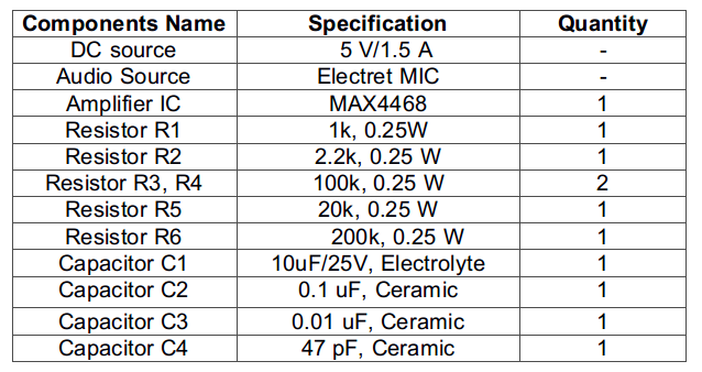

Circuit Connections –
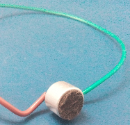
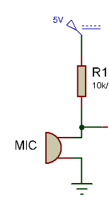
In the circuit diagram, a resistive divider network (Shown as R1 and R2 in the circuit diagram) is used to provide a fixed voltage to the MIC. A capacitor (Shown as C1 in the circuit diagram) of 10 uF is connected at the resistor’s junction point which helps in maintaining the voltage at microphone pin. The other pin of the electret microphone is connected to the common ground.

The MAX4468 IC has the following pin configuration –
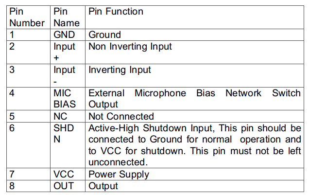
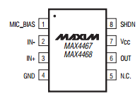
Fig. 7: Pin Diagram of MAX4468 IC
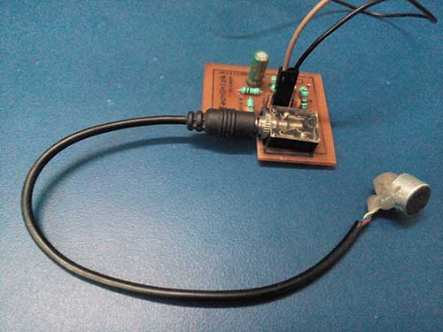
Fig. 8: Prototype of MAX4468 IC based Microphone Audio Pre Amplifier
How the circuit works –

Fig. 9: Graph of Input Waveform from Microphone observed on Digital Storage Oscilloscope
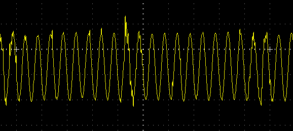
So, it can be observed that the input audio signal from the microphone is successfully leveled up to the line voltage. So, the pre-amplifier is working at its best. This pre-amplifier circuit can be used in cell phones, Microphones, Hearing Aids and Portable Audio devices.
You may also like:
Project Video
Filed Under: Electronic Projects
Filed Under: Electronic Projects



Questions related to this article?
👉Ask and discuss on Electro-Tech-Online.com and EDAboard.com forums.
Tell Us What You Think!!
You must be logged in to post a comment.