Components Required –
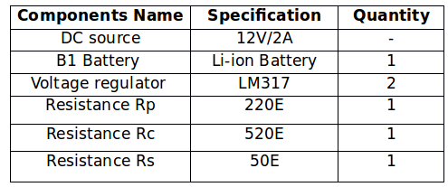
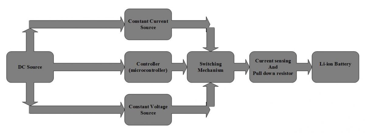

Fig. 4: Flowchart showing Charging Algorithm for Linear Regulator based 3.7 V Lithium-Ion Battery Charger
For designing the constant current source and constant voltage source for the charger circuit, following steps are followed –
Testing the Battery Specifications –
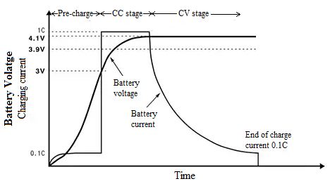
Determining design parameters for the charger circuit
Designing Constant-Current Source

I= 1.25/ Rs (Equation given in the datasheet of LM317)
Desired Current, I = 60mA
Rs= 1.25/0.06
Rs = 20 ohm (approx.)
The value of desired constant current can be changed by changing the value of Rs. As LM317 can provide a maximum current of 1.5 A, that is why the value of Rs cannot be less than 0.83E.
In the selection of any resistor, there are basically two parameters that have to be considered, one is its resistance and another is its power rating. The power rating expressed in watts depends upon the maximum current which can flow through the resistor without damaging it. So, if a low watt resistor is taken, then, the high current will heat up the resistor and damage it. So, it is equally important to determine the power rating of the resistor as well. It can be calculated as follow –
Maximum current which has to flow from the resistor Rs is 60mA.
So, Power = (voltage drop across Rs)*(maximum current across Rs)
Power = 1.25*0.06
Power = 75 mW (approx.)
Therefore, the maximum power which is dissipated by Rs is 75 mW.
As per the availability, a resistor of 0.25W or 250 mW can be used.
It must be noted that the charging circuit has been designed for a charging current of 60 mA in CC mode. But as per the charging current of a specific battery, it can be changed to a maximum value 1.25 A by changing the value of resistance Rs in the LM317 circuit.
Designing Constant Voltage Source –
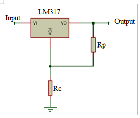
Fig. 7: Circuit Diagram of LM317 Constant Voltage Source for Lithium Ion Battery Linear Charger
For using the LM317 as a constant voltage source, a resistive voltage divider circuit is used between the output pin and the ground. The voltage divider circuit has a programming resistor (Resistor Rp) and another is output set resistor (Resistor Rs). By taking a perfect ratio of programming resistor and the output resistor, the desired value of output voltage can be determined. The output voltage Vout can be calculated by the following equation –
Vout = 1.25*(1 + (Rc/ Rp) (Equation given in the datasheet of LM317)
The typical value of resistor Rp should be from 220E to 240E for the stability of the circuit. In this circuit, the value of programming resistor Rp is taken to be 220E. Now as per the requirement, the output voltage should be 4.2V, so the value of resistor Rc will be as follow –
Desired output voltage, Vout= 4.2V
Output set resistor, Rp= 220E
Putting values of Vout and Rp in the equation,
4.2 = 1.25*(1+ (Rc / 220)
After solving the equation, value of Rc is calculated as follow –
Rc = 520 ohm (approx.)For using the LM317 as a constant voltage source, a resistive voltage divider circuit is used between the output pin and the ground. The voltage divider circuit has a programming resistor (Resistor Rp) and another is output set resistor (Resistor Rs). By taking a perfect ratio of programming resistor and the output resistor, the desired value of output voltage can be determined. The output voltage Vout can be calculated by the following equation –
Vout = 1.25*(1 + (Rc/ Rp) (Equation given in the datasheet of LM317)
The typical value of resistor Rp should be from 220E to 240E for the stability of the circuit. In this circuit, the value of programming resistor Rp is taken to be 220E. Now as per the requirement, the output voltage should be 4.2V, so the value of resistor Rc will be as follow –
Desired output voltage, Vout= 4.2V
Output set resistor, Rp= 220E
Putting values of Vout and Rp in the equation,
4.2 = 1.25*(1+ (Rc / 220)
After solving the equation, value of Rc is calculated as follow –
Rc = 520 ohm (approx.)
Therefore by using two LM317 ICs, a Constant Current Source of 60 mA and Constant Voltage Source of 4.2 V are finally designed. Both of these smaller circuits will be part of the charger circuit for the Li-ion battery.
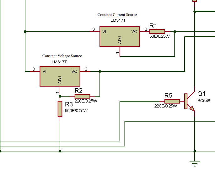
Fig. 8: Circuit Diagram of Constant Voltage Source and Constant Current Source in Lithium Ion Battery Linear Charger
It is important that the battery rated current and maximum rated voltage are must be checked before designing the charger and using the charger circuit with it. The charging voltage of the battery must be greater than its maximum rated voltage in CV mode. The battery must be charged with 0.5 C to 0.8 C charge rate. The resistor Rs must have an appropriate watt rating to prevent the resistor from any damage.
You may also like:
Project Source Code
###
//Program to *Linear regulator single 3.7V Li-ion battery charger *Charges the battery in Constant Current(CC) with 60mA current and in Constant Voltage(CV) mode with 4.2V */ /*IN/OUT Pin connection *Sense battery voltage - A0 *Sense resistor voltage - A1 *BJT for Switching state relay - 11 *BJT for isolation relay - 12 *CC mode LED - 9 *CV mode LED - 8 *Fully charged battery LED - 7 */ // They're used to give names // to the pins used: #define analogInPin_V_bat A0 // Analog input pin at battery positive #define analogInPin_I_bat A1 // Analog input pin at sense resistor #define switch_pin 11 // switching state relay #define isolation_pin 12 // Isolation pin relay //#define PowerSupply 10 // PowerSupply relay #define CC_LED 9 // LED indication for cv mode #define CV_LED 8 // LED indication for cc mode #define BAT_FULL_LED 7 // LED indication for FULLY CHARGE battery int Flag = 0; // variable to set CC and CV mode /////function declaration float senseVoltage(void); // Battery Voltage sensing float senseCurrent(float); // Charging current sensing /////Function definition /* * Function Name - senseVoltage * Function to read voltage of battery * Input parameters - none * Return - float */ float senseVoltage(){ ///read analog voltage int senseV_bat = analogRead(analogInPin_V_bat); // map it to the range of the analog out: float V_bat =(senseV_bat/1024.0)*5.0; Serial.println("currentBatteryVoltage"); Serial.println(V_bat); return(V_bat); } /* * Function Name - senseCurrent * Function to read charging current of battery * Input parameters - float * Return - float */ float senseCurrent(float currentBatteryVoltage){ ///read analog voltage float senseResistor = analogRead(analogInPin_I_bat); // map it to the range of the analog out: float senseResistorVoltage =(senseResistor/1024.0)*5.0; float actualResistor_Voltage = (senseResistorVoltage-currentBatteryVoltage); ////calculating current from voltage difference of sense resistor float I_bat = (actualResistor_Voltage)*1000; //print at serial monitor Serial.println("currentBatteryVoltage"); Serial.println(currentBatteryVoltage); Serial.println("senseResistorVoltage"); Serial.println(senseResistorVoltage); Serial.println("actualResistor_Voltage"); Serial.println(actualResistor_Voltage); Serial.println("I_bat"); Serial.println(I_bat); return(I_bat); } void setup() { // initialize serial communications at 9600 bps: Serial.begin(9600); /////////set IN/OUT pins pinMode(switch_pin,OUTPUT); pinMode(isolation_pin,OUTPUT); pinMode(CC_LED,OUTPUT); pinMode(CV_LED,OUTPUT); pinMode(BAT_FULL_LED,OUTPUT); //initially both relays are OFF digitalWrite(switch_pin,LOW); digitalWrite(isolation_pin,LOW); } void loop() { uint8_t BatteryState=0 ; // Variable to keep track of battery state //Every time eet these pin low digitalWrite(isolation_pin,LOW); digitalWrite(CC_LED,LOW); digitalWrite(CV_LED,LOW); //////////****read the analogvalues float batteryVoltage = senseVoltage(); //return battery voltage float batteryCurrent = senseCurrent(batteryVoltage); // return battery charging current if(Flag == 1) { // After CC mode enter in CV mode BatteryState = 2; Flag = 0;}// Battery enter in CV mde after CC mode else if(Flag == 2){ while(batteryVoltage>=4.0){ batteryVoltage = senseVoltage(); //check for when battery is removed or battery is discharged below 4V if(batteryVoltage <4){ Flag = 0; digitalWrite(BAT_FULL_LED,LOW); break;}}}// battery fully charged scanning for battery removed or not else if(batteryVoltage < 3.0){ //do nothing }// No Battery or bad battery,Ideal state else if(batteryVoltage<4.0 && batteryVoltage>3.0){ digitalWrite(isolation_pin,LOW); BatteryState = 1; }//charge battery in CC MODE else if(batteryVoltage >= 4.0){ BatteryState = 2; }//charge battery in CV MODE /////////////*****MODE SELECT****/////////// switch(BatteryState){ case 1: // CC MODE ///Switch ON CC mode LED and trigger relay digitalWrite(isolation_pin,HIGH); digitalWrite(switch_pin,HIGH); digitalWrite(CC_LED,HIGH); Serial.println("CC mode"); //when battery voltage is in between 3V and 4V enter in while loop while(batteryVoltage <4.0 && batteryVoltage>=3.0){ batteryVoltage = senseVoltage(); //check for when battery is charging in CC mode if(batteryVoltage>=4.0){ digitalWrite(isolation_pin,LOW); //delay to compensate switching time of relay with software delay(100); Flag = 1; digitalWrite(CC_LED,LOW); break;} //check for when battery is removed else if(batteryVoltage<3.0){ digitalWrite(isolation_pin,LOW); digitalWrite(switch_pin,LOW); digitalWrite(CC_LED,LOW); Serial.println("EXIT "); //delay to compensate switching time of relay with software delay(100); break;} } break; /// exit case 1. case 2: // CV MODE ///Switch ON CV mode LED and trigger relay digitalWrite(isolation_pin,HIGH); digitalWrite(CV_LED,HIGH); Serial.println("Cv mode"); batteryVoltage = senseVoltage(); //when battery voltage is in 4V enter in while loop while(batteryVoltage >=4.0 ){ batteryVoltage = senseVoltage(); batteryCurrent = senseCurrent(batteryVoltage); //check for when battery is charging in CV mode if(batteryCurrent < 10){ digitalWrite(isolation_pin,LOW); //delay to compensate switching time of relay with software delay(100); digitalWrite(CV_LED,LOW); digitalWrite(BAT_FULL_LED,HIGH); Flag = 2; Serial.println("Battery charged"); break;} //check for when battery is removed else if(batteryVoltage<3.0){ digitalWrite(isolation_pin,LOW); //delay to compensate switching time of relay with software delay(100); digitalWrite(CV_LED,LOW); break;} } break; /////end of switch case 2. } }###
Circuit Diagrams
Project Video
Filed Under: Electronic Projects, Featured Contributions
Filed Under: Electronic Projects, Featured Contributions




Questions related to this article?
👉Ask and discuss on EDAboard.com and Electro-Tech-Online.com forums.
Tell Us What You Think!!
You must be logged in to post a comment.