As per the first article in this series on designing filters, we learned that they are important for clear communication. The main function of filters is to suppress or filter out components from mixed frequency signals. Essentially, they allow a certain range of frequencies to pass, which is known as “pass bend,” rejecting (or suppressing) all other frequencies that are called “stop bend.”
The cut-off frequency is the parameter that separates these two bends. Depending on the pass and stop bends, there are four types of filters (low-pass, high-pass, band-pass, and band-reject filters). In this tutorial, we discuss low-pass filters or LPFs.
LPFs allow all of the frequencies that are lower than its cut-off frequency to pass while stopping all others.
The first order of a low-pass filter
- Step 1: Select or choose the required cut-off frequency. For example, let’s suppose we want the filter to pass all of the frequencies below 15 kHz, which are those that are audible to the human ear. This means: FC = 15000 Hz
- Step 2: Next, we must assume the required value of the capacitor. It should be less than 0.1 micro Farad. This is required for better frequency stability. In this case, let’s assume C as 4.7 nF (nano farad)
- Step 3: Now calculate the value of resistance from the equation.

Example of the calculations required to find the resistance for the first order of a low-pass filter.
Our assumption for the capacitance value of 4.7 nF looks good (or, at least, OK!). But what if the calculated value of R is much less than 1 K? We’d then have to assume another value for the capacitor because the value of R should never be less than 1.

- Step 4: Choose the required pass-band gain. Let’s go with 2. Now, form the equation…
Af = 1 + (R2 / R1)
2 = 1 + (R2 / R1)
R2 / R1 = 1
R2 = R1

A screenshot of the calculations required to find the resistance for the low-pass filter.
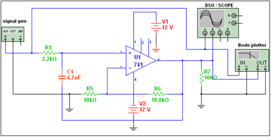
It’s worth noting that the op-amp is an active component and it requires +ve and -ve biasing voltages. It’s also possible to test the circuit by applying input through the signal generator and observing the output on the DSO or oscilloscope, as well as the bode plotter.

A circuit diagram of the LM741 OPAMP IC-based first order of a low-pass filter.
Note: I have simulated the above circuit in NI’s multisim 11 software. The schematic design is also prepared using the same software. The software is available as a free one-month trial period from National Instrument’s (NI) website. The below circuits are also prepared using the multisim 11 software and tested in it.
The second order of a low-pass filter
- Step 1: For simplicity let’s assume: R1 = R2 = R and C1 = C2 = C
- Step 2: Select the desired cut-off frequency. In this case, let’s use: FC = 1 kHz = 1000 Hz
- Step 3: Next, assume the capacitor value C as 10nF
- Step 4: Calculate the value of the R from

The calculations required to find the resistance and pass-band gain for the second order of the low-pass filter.
Here’s the final design:

A circuit diagram of the LM741 OPAMP IC-based second order of the low-pass filter.
Higher-order low-pass filters
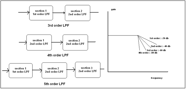
Higher-order filters, such as the third, fourth, or fifth order filters can be designed by cascading the first and second-order LPF sections. Increasing the order will increase the stop-band attenuation by 20 DB.
The figure below illustrates this concept. By using a higher-order filter, it’s possible to receive a better response with the stiff slop. For example, we may get a response such as an idle LPF.
The cut-off frequency for all of the stages is the same, which means the RC value of all of stages is also the same.

An overview of the third, fourth, and fifth order of a low-pass filter.
Project Video
Filed Under: Electronic Projects
Filed Under: Electronic Projects


Questions related to this article?
👉Ask and discuss on Electro-Tech-Online.com and EDAboard.com forums.
Tell Us What You Think!!
You must be logged in to post a comment.