Engineers Garage

  • Projects and Tutorials
    • Electronic Projects
      • 8051
      • Arduino
      • ARM
      • AVR
      • PIC
      • Raspberry pi
      • STM32
    • Tutorials
    • Circuit Design
    • Project Videos
    • Components
  • Articles
    • Tech Articles
    • Insight
    • Invention Stories
    • How to
    • What Is
  • News
    • Electronic Products News
    • DIY Reviews
    • Guest Post
  • Forums
    • EDABoard.com
    • Electro-Tech-Online
    • EG Forum Archive
  • Digi-Key Store
    • Cables, Wires
    • Connectors, Interconnect
    • Discrete
    • Electromechanical
    • Embedded Computers
    • Enclosures, Hardware, Office
    • Integrated Circuits (ICs)
    • Isolators
    • LED/Optoelectronics
    • Passive
    • Power, Circuit Protection
    • Programmers
    • RF, Wireless
    • Semiconductors
    • Sensors, Transducers
    • Test Products
    • Tools
  • EE Resources
    • DesignFast
    • LEAP Awards
    • Oscilloscope Product Finder
    • White Papers
    • Webinars
  • EE Learning Center
    • Design Guides
      • WiFi & the IOT Design Guide
      • Microcontrollers Design Guide
      • State of the Art Inductors Design Guide
  • Women in Engineering

Digital alarm clock with 8051(89c51) microcontroller

By EG Projects

Digital alarm with 8051(89c51,89c52) microcontroller is a comprehensive project. Comprehensive in the form that its code is very lengthy. Programming is not an easy stuff for every one , and when it comes to program a microcontroller it becomes more complex to write a code for desired output if you are not familiar with the basics of programming. Digital alarm with 8051(89c51,89c52) microcontroller is an extension of digital clock with 8051(89c51,89c52) microcontroller project. The alarm works in the same way as your digital watches and mobile phone alarms works. Well all alarms works same 😀 

8051 microcontroller digital alarm – Project requirements

  • 8051(89c51 or 89c52) microcontroller
  • alarm(I used buzzer) 
  • 16×2 lcd
  • Potentiometer/variable resistor (For setting lcd contrast)
  • 4×3 keypad(You can also use 4×4. 4×4 contains 4×3 in it :D)
  • Crystal(11.0592 MHz)
  • Bread board(Designing circuit. You can also design circuit on PCB(Printed circuit board))

Tutorials regarding 8051 digital alarm clock project

Its not possible to explain each and every statement of code. For example 16×2 lcd interfacing with 8051 microcontroller or 4×4 numeric keypad interface with 8051 microcontroller or how to generate proper time delay using internal timers of 89c51 microcontroller can not be explained in a single tutorial. So i made multiple tutorials on each component which is part of this project.   

  • ​How to generate one second delay with 8051 microcontroller.
  • How to generate one minute delay with 8051 microcontroller. 
  • How 16×2 lcd works.
  • Digital clock with 8051 microcontroller.​

​
All the above tutorials play a vital role in 8051 digital alarm clock project. I will say the code of all the above tutorials is part of this project. I just arranged the code in sequence with some minor modifications and made a stream line code flow to achieve digital alarm clock functionality.   

Digital alarm clock – Code flow

when you first run the program you have to set the clock time same like the digital clock project(Link given above). Once you set the clock time it will start running for ever unless you reset the microcontroller. Now when ever you want to set an alarm press the button located in first coulomb and at fourth row of 4×3 keypad. Pressing the button will lead to an event which displays messages on 16×2 lcd to set hours and minutes. Now set alarm time.

Note: No external RTC(real time clock) is interfaced with 8051 microcontroller for time calculation. Rather internal timers of 89c51 mirocontroller are utilized for producing clock time(Visit above digital clock with 89c51 tutorial). 

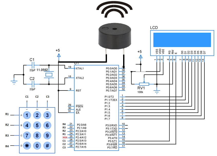
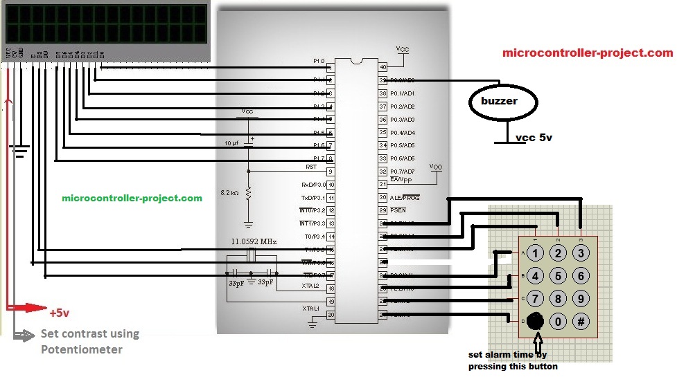
89c51 microcontroller digital alarm – Circuit diagram

The circuit for the project is very simple. Connect 16×2 lcd with Port 1 of 8051 (89c51 or 89c52) microcontroller. Rd(read) Wr(write) and En(enable) signals are provided to 16×2 lcd using port 3 pins 5 , 6 & 7 of 8051 (89c51 or 89c52) microcontroller. Port 0 pin 0 is used to operate buzzer when ever alarm time reached to its matched clock time. Port 2 is dedicated for our 4×3 keypad. Rows are connected to pin 0, 1 ,2 & 3 of port 2. Coulombs are connected to pins 5 , 6 & 7 of port 2. Rest of the connections are simple apply 5v to pin 40 and pin 31. Connect crystal 11.0592 MHz to pins 18 and 19. Ground pin 20. Connect reset button to pin 9. 
8051 microcontroller digital alarm clock

8051 microcontroller digital alarm clock

Picture

89c51 microcontroller digital alarm clock – Project code

Coming to the code. First i included the necessary header file reg52.h. This header file should be included when ever you are writing and compiling your 8051 microcontroller program in keil ide. It includes all the necessary linker and debuggers for 8051 microcontroller configuration.

Then keypad() function is declared. This function scans the keys pressed on the 4×3 keypad. Next comes tochar() function. It is used to deal with integer type numbers to be displayed on the 16×2 lcd. Integer numbers must be converted to 8-bit character format for displaying on 16×2 lcd.

Then single bits of ports are declared for connecting our buzzer and 4×3 keypad. Next character arrays are declared they are used as messages to be displayed on 16×2 lcd on suitable conditions. delay() function is used to generate some delay for suitable purposes. lcdcmd() function is sending commands to lcd. lcddata() function is sending and printing data on lcd screen. checkconditions() function is checking conditions like if seconds reached to 60 increment the minute, if minutes reached to 60 increment hour, check if clock reached the alarm time ring the buzzer.

clockdelay() function is producing seconds, minutes and hours for us. lcdinit() initializing the lcd. settime() function is setting time of clock on every reset of the program. User have to input the time using 4×3 keypad. start() function is printing the time on 16×2 lcd at start of the program execution.
        

The above tutorials are very important if you want to understand the functions used in the code. If you don’t care about code than just burn the hex code make the circuit and enjoy your creation 😀    

The alarm is 12 hours alarm which means you can put-on alarm for maximum next 12 hours period. Do not enter hours greater than 12 and do not enter minutes greater than 60. If you want to make the alarm more intelligent just insert more functions in it like set alarm for am or pm time. Do some other work when ever clock time reaches the alarm time like switch on a bulb, start your water motor to fill the tank or switch off the oven. If you are really willing to do some extra stuff than go a head and give me your feedback. 
Download the project code and hex file compiled in keil Uvision-2. If you have any questions regarding code or any thing just leave a comment below.Your comments are highly apreciated.

Digital alarm code


Filed Under: 8051 Microcontroller, Microcontroller Projects


Questions related to this article?
👉Ask and discuss on EDAboard.com and Electro-Tech-Online.com forums.


Tell Us What You Think!! Cancel reply

You must be logged in to post a comment.

HAVE A QUESTION?

Have a technical question about an article or other engineering questions? Check out our engineering forums EDABoard.com and Electro-Tech-Online.com where you can get those questions asked and answered by your peers!


Featured Tutorials

  • Introduction to Brain Waves & its Types (Part 1/13)
  • Understanding NeuroSky EEG Chip in Detail (Part 2/13)
  • Performing Experiments with Brainwaves (Part 3/13)
  • Amplification of EEG Signal and Interfacing with Arduino (Part 4/13)
  • Controlling Led brightness using Meditation and attention level (Part 5/13)
  • Control Motor’s Speed using Meditation and Attention Level of Brain (Part 6/13)

Stay Up To Date

Newsletter Signup

Sign up and receive our weekly newsletter for latest Tech articles, Electronics Projects, Tutorial series and other insightful tech content.

EE Training Center Classrooms

EE Classrooms

Recent Articles

  • EdgeLock A5000 Secure Authenticator
  • How to interface a DS18B20 temperature sensor with MicroPython’s Onewire driver
  • Introduction to Brain Waves & its Types (Part 1/13)
  • An Embedded Developer’s Perspective on IOT (Internet of Things)
  • Understanding NeuroSky EEG Chip in Detail (Part 2/13)

Most Popular

5G 555 timer circuit 8051 ai Arduino atmega16 automotive avr bluetooth dc motor display Electronic Part Electronic Parts Fujitsu ic infineontechnologies integratedcircuit Intel IoT ir lcd led maximintegratedproducts microchip microchiptechnology Microchip Technology microcontroller microcontrollers mosfet motor powermanagement Raspberry Pi remote renesaselectronics renesaselectronicscorporation Research samsung semiconductor sensor software STMicroelectronics switch Technology vishayintertechnology wireless

RSS EDABOARD.com Discussions

  • Pic 16f877A Hex file
  • Need help to choose accelerometer
  • 7 segment display connections
  • finding attenuation coefficient in CST
  • Effect of variable gain amplifier and LNA on the input RF signal's phase

RSS Electro-Tech-Online.com Discussions

  • NOR gate oscillator in LTspice not working
  • How to designing a battery charging indicator circuit for 18650 battery pack
  • ICM7555 IC duty cycle limit at high frequency?
  • I've DESTROYED 3 piezo buttons :((((
  • led doorbell switch
Engineers Garage
  • Analog IC TIps
  • Connector Tips
  • DesignFast
  • EDABoard Forums
  • EE World Online
  • Electro-Tech-Online Forums
  • Microcontroller Tips
  • Power Electronic Tips
  • Sensor Tips
  • Test and Measurement Tips
  • 5G Technology World
  • About Us
  • Contact Us
  • Advertise

Copyright © 2022 WTWH Media LLC. All Rights Reserved. The material on this site may not be reproduced, distributed, transmitted, cached or otherwise used, except with the prior written permission of WTWH Media
Privacy Policy | Advertising | About Us

Search Engineers Garage

  • Projects and Tutorials
    • Electronic Projects
      • 8051
      • Arduino
      • ARM
      • AVR
      • PIC
      • Raspberry pi
      • STM32
    • Tutorials
    • Circuit Design
    • Project Videos
    • Components
  • Articles
    • Tech Articles
    • Insight
    • Invention Stories
    • How to
    • What Is
  • News
    • Electronic Products News
    • DIY Reviews
    • Guest Post
  • Forums
    • EDABoard.com
    • Electro-Tech-Online
    • EG Forum Archive
  • Digi-Key Store
    • Cables, Wires
    • Connectors, Interconnect
    • Discrete
    • Electromechanical
    • Embedded Computers
    • Enclosures, Hardware, Office
    • Integrated Circuits (ICs)
    • Isolators
    • LED/Optoelectronics
    • Passive
    • Power, Circuit Protection
    • Programmers
    • RF, Wireless
    • Semiconductors
    • Sensors, Transducers
    • Test Products
    • Tools
  • EE Resources
    • DesignFast
    • LEAP Awards
    • Oscilloscope Product Finder
    • White Papers
    • Webinars
  • EE Learning Center
    • Design Guides
      • WiFi & the IOT Design Guide
      • Microcontrollers Design Guide
      • State of the Art Inductors Design Guide
  • Women in Engineering